E-Retracts
|
|
E-Retracts |
|
|
Assembly Instructions
User's Manual
BUY ONE NOW! VIDEO!
LATEST NEWS!
The final design and firmware for this project has been sold to a retract
manufacturer. Unfortunately, this manufacturer does not plan to manufacture or
sell actuators/retrofit kits, even though I tried talking them into it. Another
good friend is thinking about possibly manufacturing his own retrofit kits in
the near future... I'll be sure to post any info re: them on my webpages.
The following information
provided is not that of the final design, but is that of an adequate, working
design, as is provided as-is. Unfortunately, I can not provide any information
on the PIC firmware as the code/routines have been sold. Use of this
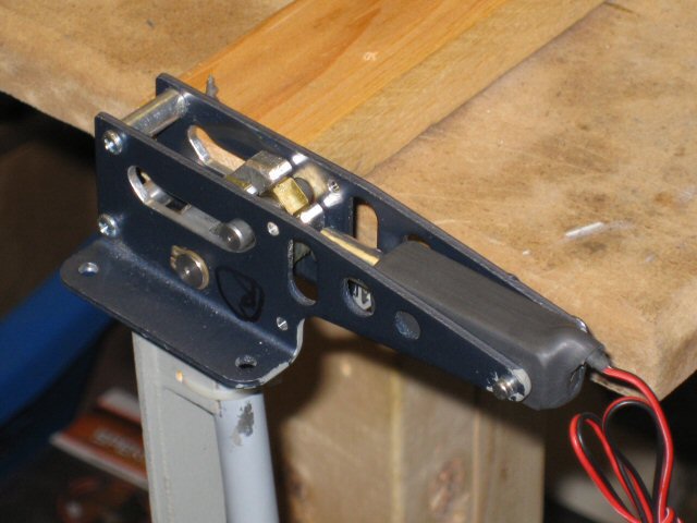
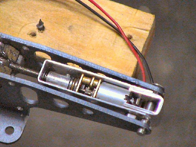
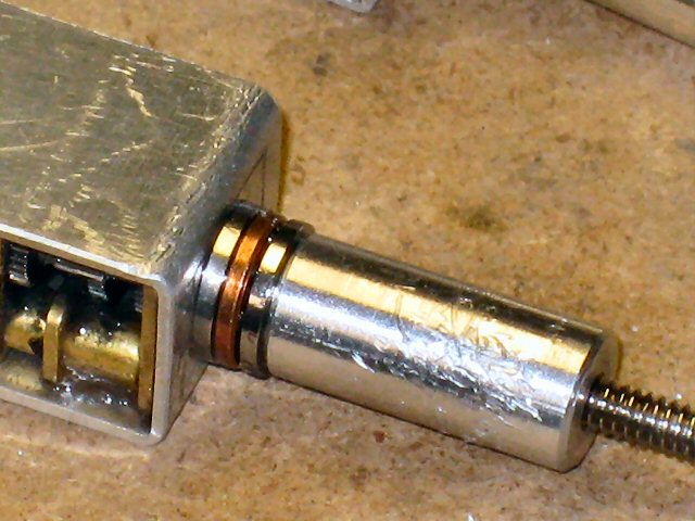
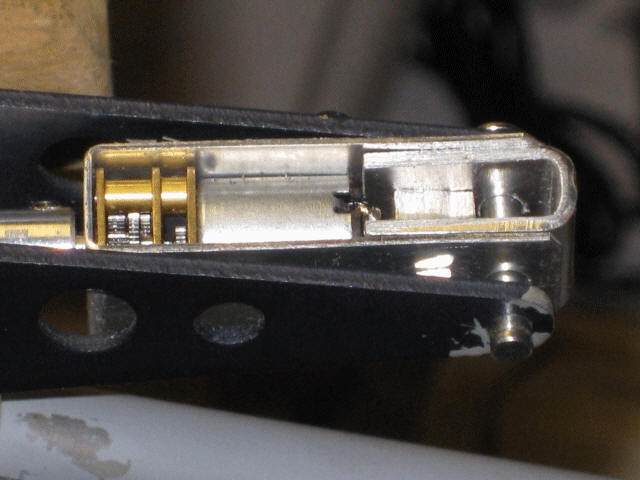
information/design is prohibited in commercial products. I've come up with an even better design that isolates the push/pull forces of the coupler form the shaft of the gear motor. Most of the binding I've seen in this setup (stalling of motors) appears to be in the gearbox itself. The force of the jackscrew coupler is placed onto the output shaft of the motor, driving it hard in to either gear back-plate. The new clam-shell design captures the coupler and motor using a flange bearing on the front side and a thrust bearing on the motor side. The aluminum coupler loosely fits onto the output shaft of the gear motor ("D" shaped shaft). The coupler's set screw is set loosely, allowing the motor's shaft to slide in and out of the coupler. This allows the two bearings to take the axial forces, rather than placing them on the output shaft of the gear motor (i.e. adding friction/binding). MORE INFO COMING SOON!
01/20/2010
MECHANICS
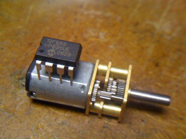
These motors have a heft of a torque for their small
size. Key specs include 625 RPM (at 5-6 volts) a 100 mA free-run current,
a torque of 15 oz-in (1.0 kg-cm) and a stall current of 1.6 A. The other
key feature of these motors are they use all metal gears, such to avoid stripped
gears during high loads and stalls. Even though a torque rating of 15
oz-in, these will be used to spin a 4-40 threaded rod, giving a torque gain of
x40 or 600 oz-in.
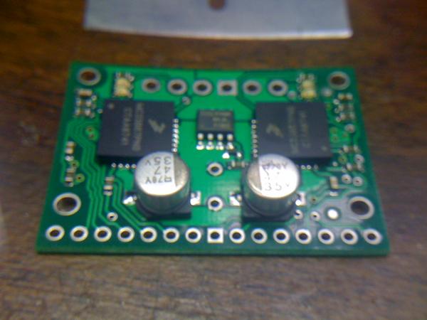
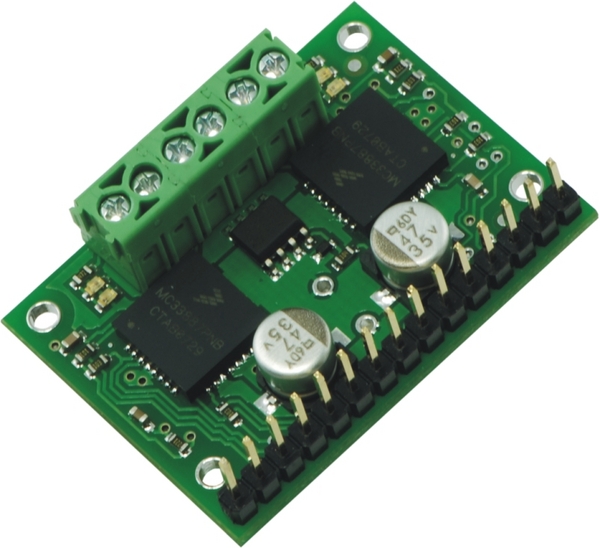
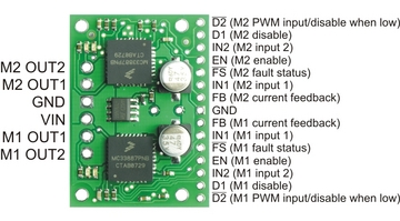
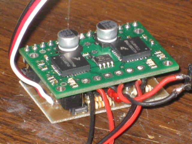
ELECTRONICS http://www.pololu.com/catalog/product/712 This nicely made Pololu breakout board uses 2 Freescale Semiconductor MC33887 motor driver integrated circuits, making it easy easy to connect two brushed DC motors running from 5 to 28 V and drawing up to 5 A (peak) each to your project.
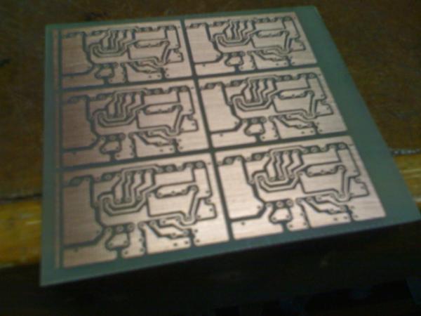
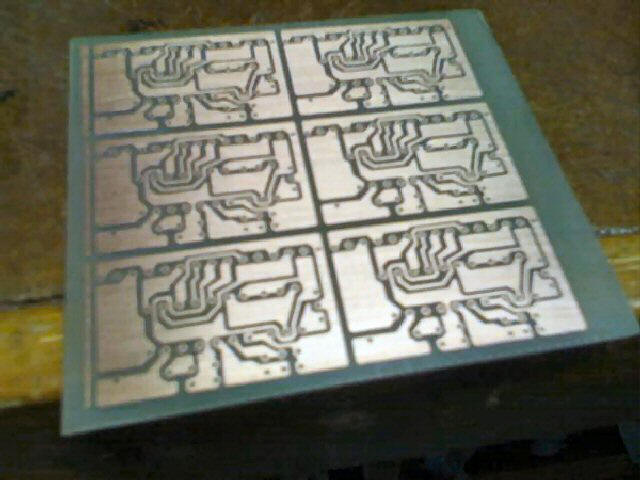
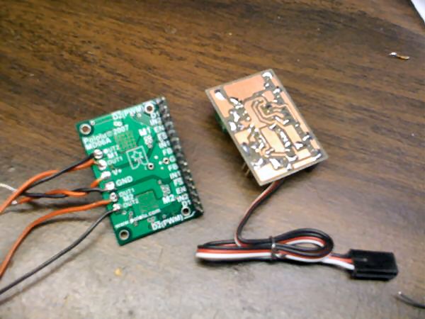
Below are a few pictures of the PCB I made which allows the Pololu board to simply be plugged in. This control board controls both H-Bridge motor controls (3 wires each, two for motor direction control and one for the current feedback signal). Included on the control board is an LED, a pushbutton switch (for stall learning function), two servo PWM outputs signals (for controlling retract wheel doors/hatches), a jumper (for getting into program mode: retract delays/stagger, retract door servo sequence enabling, and other functions I come up with...)
I doubt I'll ever sell assembled kit but if there
are tinkerers out there that want to experiment, drop and email... I can
probably sell you at least a programmed PIC and maybe a PCB if I make some
extras. Older PCBs are shown below....
Design Criteria Summary:
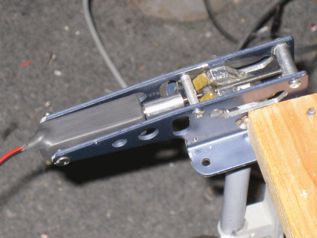
1) Design small but powerful gear system for driving
existing Robart gear (i.e. replacement to air cylinders)
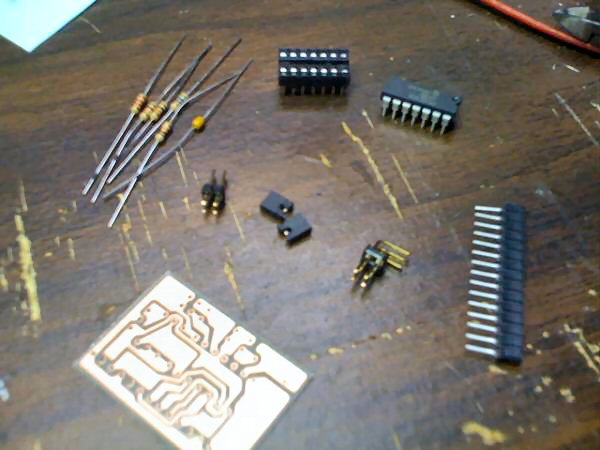
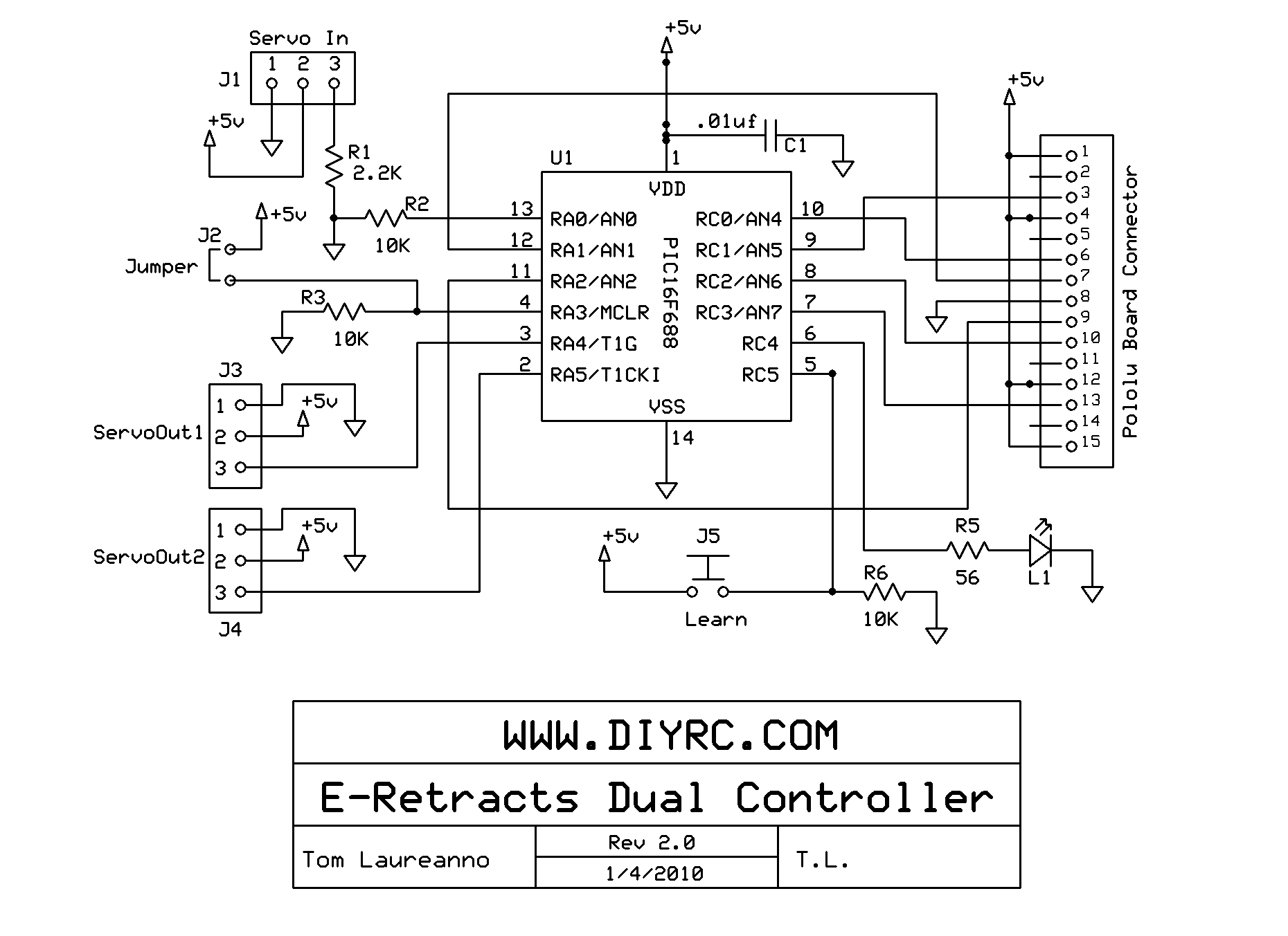
1) One
(1) PIC 16F688 microcontroller (preprogrammed with "E-Retract" code) Below is the latest schematic that matches the new/latest PCB...
* E-RETRACT BUILDING INSTRUCTIONS *
(Sorry, Under Construction!)
Testing and Operation Instructions... Download the E-Retract User's Manual below (in PDF format... Adobe reader is required) The web version of the manual is shown below: (Sorry, Under Construction!)
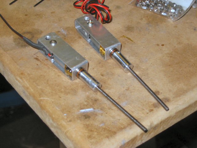
Programming & Operating the "E-Retract"... The E-retracts system consists of two motorized actuators and the control electronics (Pololu H-Bridge breakout board and the PIC mating board I designed). The control system allows the system to control two separate actuators while also incorporating dual feedback controls for sensing stall currents of both both. The controller must first "learn" the stall currents of both motors such that the controller's current sensor does not prematurely shut down the motor during normal operation. This "learning" is enables by powering up the controller while having the "learn" button pressed in. Upon being powered up, you will see the controller actuate both actuators, driving them in both directions, while stalling the motor (this is where the learn function measures the highest current draw and stores it in memory).
One option on the controller is a jumper that either enables (on) or disables (off) the retract wheel door/hatch servo functions (2 servo outputs). To activate the wheel stagger function, you can simply tap the "learn" button once while powered up to toggle this stagger function either on or off. ... more coming soon....
WANT TO BUY AN E-RETRACT CONTROLLER KIT/PARTS?
E-Retract Controller -
Pre-Programmed PIC Only
E-RETRACT FAQ Q1. ...
|
||||||||||||||||||