IMPORTANT NOTE:
The PICAXE Aiptek switch design needs to add a 10K resistor from Pin#2 (the programming input pin on the Picaxe) to ground, as to not let it "float". I will be making these webpage updates shortly... (see updated schematic below)
|
PICAXE Projects: Aiptek R/C Switch |
|||||
|
|
|
|
|
||
Note: All pictures that follow are
"clickable". Clicking on them will show you an enlargement!
![]() PURCHASE
AN "AIPAXE" R/C SWITCH NOW!!
PURCHASE
AN "AIPAXE" R/C SWITCH NOW!!
![]()
![]() See
how to install this in an Aiptek 1.3 SD Camera !
See
how to install this in an Aiptek 1.3 SD Camera !
![]()
IMPORTANT NOTE:
The PICAXE Aiptek switch design
needs to add a 10K resistor from Pin#2 (the programming input pin on the Picaxe)
to ground, as to not let it "float". I will be making these webpage
updates shortly... (see updated schematic below)
A lil' history ...
 As if we haven't seen enough Aiptek R/C switches, here is yet another, this time designed
around a revolutionary, easy-to-program microcontroller called the "PICAXE".
Rather than having to program a bare PIC in a special programmer and writing PIC
code, this design allows you to program it in a rather powerful Basic-like
language and as for download, you use two resistors and a 9-pin serial port on
your computer. Since the design is based upon a Flash PIC (PIC12F683), you
can continually download new code, allowing for experimentation and prototyping.
As if we haven't seen enough Aiptek R/C switches, here is yet another, this time designed
around a revolutionary, easy-to-program microcontroller called the "PICAXE".
Rather than having to program a bare PIC in a special programmer and writing PIC
code, this design allows you to program it in a rather powerful Basic-like
language and as for download, you use two resistors and a 9-pin serial port on
your computer. Since the design is based upon a Flash PIC (PIC12F683), you
can continually download new code, allowing for experimentation and prototyping.
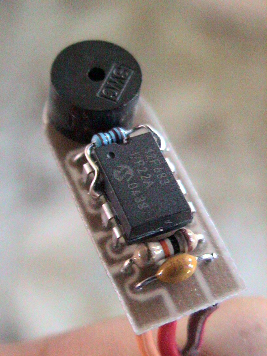
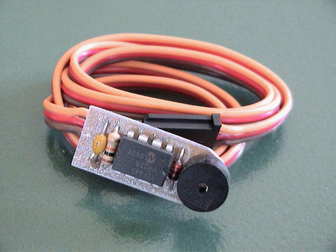
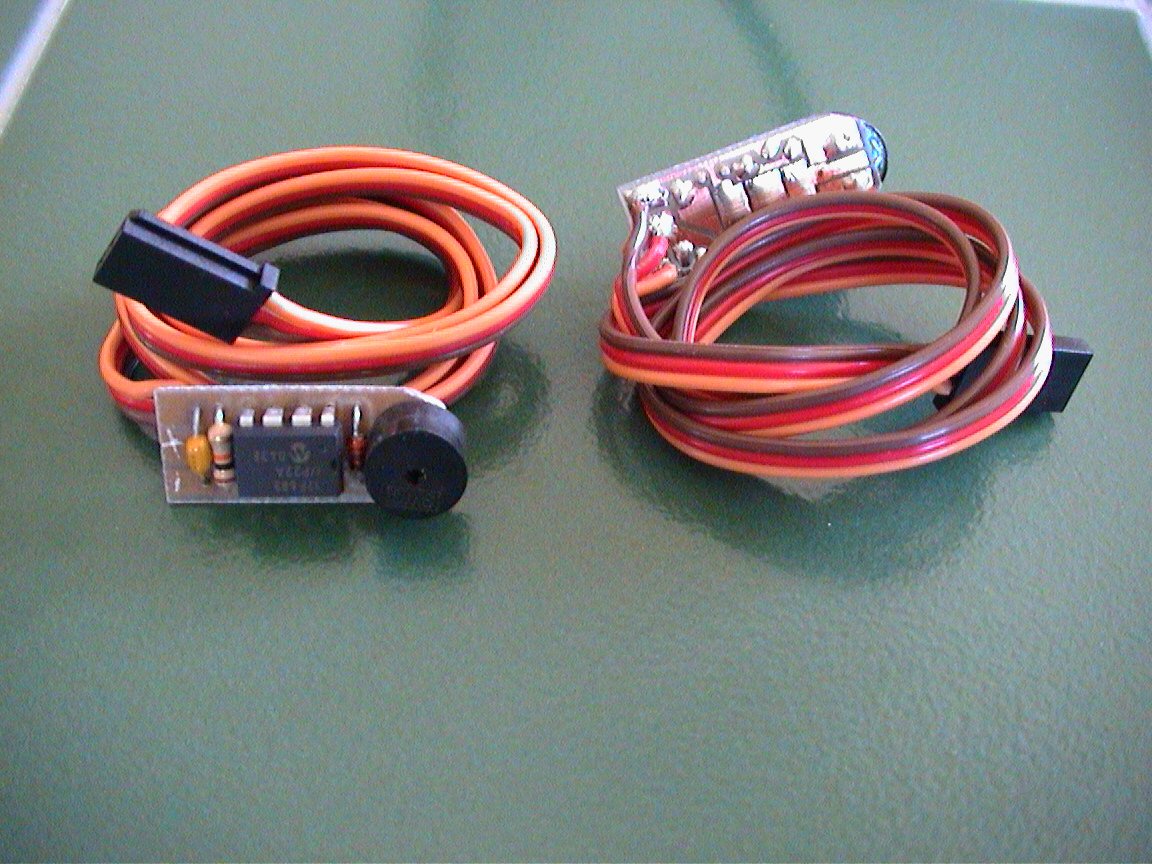
I designed this nifty circuit using a preprogrammed PICAXE controller, a piezo element, two 10K ohm resistors, a .1uF capacitor and a 1N4148 signal diode. This neat device allows you to program switch-on points and switch/stick direction. The unit even stores the settings in internal memory. If the circuit senses that there exists no servo signal, a piezo beeper is sounded. This can be used as a model-finder. Next time your plane gets lost in the high grass, you can simply turn off your transmitter and a second later, the beeper continually emits beeps, allowing you to locate the downed plane. The circuit also has a built in trigger delay that does not allow the Aiptek camera to attempt to take pictures faster than it can store them to memory. These user-programmable functions are very easy to use. The firmware code on the other hand can be challenging but not all that difficult to understand, especially if you have messed around with Basic Stamp coding in the past.
Newer pictures coming soon !! (new circuit/PCB design as shown below)
..more coming soon


![]() Latest
pictures are shown below (Version 12):
Latest
pictures are shown below (Version 12):
Below are a few pictures that show you how this AipAxe switch installs in an Aiptek 1.3M digital camera...
![]() See
how to install this in an Aiptek 1.3 SD Camera !
See
how to install this in an Aiptek 1.3 SD Camera !
![]()
Design Criteria Summary:
1) ...more coming soon
![]()
1) ...more coming soon
Building Instructions...
...more coming soon
Click here to View Code (Sorry, firmware is no longer freeware)
Click here to Download Code (Sorry, firmware is no longer freeware)
![]() CHECK
BACK LATER.... I WILL BE ADDING FREE CODE "SNIPPETS" !!
CHECK
BACK LATER.... I WILL BE ADDING FREE CODE "SNIPPETS" !!![]()
Testing and Operation Instructions...
![]() CLICK
HERE TO DOWNLOAD THE MANUAL (MS WORD)
CLICK
HERE TO DOWNLOAD THE MANUAL (MS WORD)![]()
(THIS IS FOR THE NEWER FIRMWARE)
1. With both the transmitter and receiver powered off, plug the camera's servo plug into the receiver channel # to which you want to use as your shutter control. This can either be a switch or joystick.
2. Power up the transmitter first and position the switch or stick (corresponding to channel on receiver which switch is connected) in the direction to which you would want to be the OFF position (the position where no picture is taken).
3. Now power up the receiver and
you will hear the switch and Aiptek camera eventually power up (beeps).
About a second or two after that (as the circuit analyzes the receiver servo
signal), you will hear a "Ready" beep (2 low beeps then a longer high beep)
indicating that the circuit is ready for operation (no others beeps should be
heard until you take a picture).
IS THAT SIMPLE ?
4. To take a picture, move the joystick/switch to the On position and then return it to the opposite (OFF) position. You should hear the switch circuit output a low to high chirp, and then quickly hear the Aiptek camera take a picture (also visible on the Aiptek display). If the transmitter's switch/joystick if left in the ON position, the switch circuit will make the Aiptek camera take a picture approximately every 7 seconds, until the switch/joystick is returned to the OFF position.
5. If you were to turn off the transmitter while the receiver and camera are powered up, the switch circuit will eventually continually beep, indicating that there exists no servo signal. This is the built-in "Model-Finder" alarm that will hopefully help you locate a downed aircraft. Just power off the transmitter and the circuit will begin to beep.
6. Upon powering up the transmitter, you will eventually hear a "Ready" beep (2 low beeps then a longer high beep) indicating that the circuit is ready for operation once again.
(THIS IS FOR THE OLDER FIRMWARE)
1. With both the transmitter and receiver powered off, plug the camera's servo plug into the receiver channel # to which you want to use as your shutter control. This can either be a switch or joystick.
2. Power up the receiver and you will hear the Aiptek camera eventually power up (beeps). A few seconds later, you will hear the camera switch circuit power up (beeps). The circuit will then continually beep, indicating that there exists no servo signal, since the transmitter is off. This is the built-in "Model-Finder" alarm that will hopefully help you locate a downed aircraft. Just power off the transmitter and the circuit will begin to beep.
3. After the camera and switch has powered up, (with transmitter still powered OFF) position the transmitter's switch or joystick (the control corresponding to the channel # you have the camera plugged into) such that it is in the ON position, that is, the position you want in order to take a picture.
4. After this trigger position is set on the transmitter, power on the transmitter and you should hear 2 high beeps from switch circuit. Following these beeps, you should then hear a low beep every 2 second or so. This is indicating that it is waiting for you to arm the camera switch. You do this by positioning the switch/joystick to the OFF position (the position for which the camera will cease taking pictures). Upon repositioning the switch/joystick, you will hear a "Ready" beep (2 low beeps then a longer high beep) indicating that the circuit is ready for operation (no others beeps should be heard until you take a picture).
5. To take a picture, move the joystick/switch to the On position and then return it to the opposite (OFF) position. You should hear the switch circuit output a low to high chirp, and then quickly hear the Aiptek camera take a picture (also visible on the Aiptek display). If the transmitter's switch/joystick if left in the ON position, the switch circuit will make the Aiptek camera take a picture approximately every 7 seconds, until the switch/joystick is returned to the OFF position.
The circuit saves the last
user-programmed settings (trigger point and trigger direction) for use next
time you power it up. In order for the circuit to use these saved settings,
you MUST power up the transmitter before powering up the camera and receiver.
If you do not, you will have to reprogram the settings, which only takes 5
seconds the most.
Aiptek cameras can be
funny in that some are particularly sensitive to input voltage. Most Aiptek
cameras
I have modified work fine on 5V and even 5.5 volts.
If you try to power up
the camera from the receiver and the receiver is powered using 5 cells (6
volts), the camera will probably not turn on, and you in fact might damage the
PIC switch circuit. Some work, some dont. It is
highly recommended that you power up the receiver/camera using either a 4 cell
battery pack (4.8-5.2 volts) or use a Battery Elimination Circuit (BEC) or
voltage regulator that outputs a regulated 5 volts.
When you connect the
camera up to your computer to download pictures (via USB cable), the camera
and switch circuit are powered up. Because the circuit senses NO servo
signal, the model-finder alarm will beep continuously as you are downloading
pictures. The download process is not affected by this beeping.
Once the downloading is complete, simply unplug the USB cable from the camera.
This mod originally was
designed such that the camera could still be powered and operated with two AAA
batteries. After modifying a bunch of these cameras, I have noticed that
some work normally with batteries installed but some do not. I therefore
can not guarantee that the camera will operate properly with batteries
installed. The intention of this modification was to make an R/C
controlled aerial camera using a miniature hand-help digital camera. I
can guarantee that this mod will do just that!
There has been rare occurrences where an Aiptek camera can simply go "berserk"...., i.e. continual beeping or just does not work at all (indicated some times by all "eights" (888) in the camera display). In this case, it is good to reset the camera by hold down the "mode" and "shutter" buttons simultaneously for several seconds until a beep is heard (do this while camera is powered up). Removing power for a few seconds and reapplying has some times fix the problem too.
**** VERY LIMITED
QUANTITIES ARE AVAILABLE ****
Please
email me regarding product
availability before sending money....
![]()
"PICAXE is a trademark of Revolution Education Ltd (www.picaxe.co.uk)"