A lil' history ...
 This
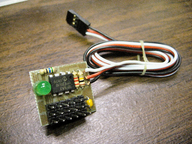
project is a simple 3-Servo sequencer triggered using an R/C signal.
The design is based around a PIC12F683 microcontroller and the idea grew out of a
discussion with a recent customer (
http://www.scaleparachutesystems.com). The servo sequencer
controls up to 3 servo channels (2 servos can be connected to each of
the 3 outputs). Upon initially powering up the circuit the
controller will control all three servos such that all 3 are in their
fully counter-clockwise direction. The sequencer is triggered
using a spare servo channel on your R/C receiver. Normally you
could use the landing gear channel (Ch #5) and control this using the
gear switch on your transmitter.
This
project is a simple 3-Servo sequencer triggered using an R/C signal.
The design is based around a PIC12F683 microcontroller and the idea grew out of a
discussion with a recent customer (
http://www.scaleparachutesystems.com). The servo sequencer
controls up to 3 servo channels (2 servos can be connected to each of
the 3 outputs). Upon initially powering up the circuit the
controller will control all three servos such that all 3 are in their
fully counter-clockwise direction. The sequencer is triggered
using a spare servo channel on your R/C receiver. Normally you
could use the landing gear channel (Ch #5) and control this using the
gear switch on your transmitter.
 If
you power up the circuit and find the LED lit, this means the
switch/trigger is in the ON position so switch it so it is OFF (this
can be reversed on your computerized transmitter if you want to change
the ON/OFF switch positions). To trigger the 1st sequence, you would
toggle the switch from OFF to ON (LED lights), then back to OFF (LED
goes off). In doing this, you should see servo#1 go from fully
counter-clockwise to fully clockwise (servo#2 and servo#3 hold their
current positions). To trigger the 2nd sequence, you would again
toggle ON/OFF the switch and in doing so you should see servo#2 go
from fully counter-clockwise to fully clockwise (servo#3 holds its
current positions). To trigger the
If
you power up the circuit and find the LED lit, this means the
switch/trigger is in the ON position so switch it so it is OFF (this
can be reversed on your computerized transmitter if you want to change
the ON/OFF switch positions). To trigger the 1st sequence, you would
toggle the switch from OFF to ON (LED lights), then back to OFF (LED
goes off). In doing this, you should see servo#1 go from fully
counter-clockwise to fully clockwise (servo#2 and servo#3 hold their
current positions). To trigger the 2nd sequence, you would again
toggle ON/OFF the switch and in doing so you should see servo#2 go
from fully counter-clockwise to fully clockwise (servo#3 holds its
current positions). To trigger the
 3rd
sequence, you would again toggle the switch ON/OFF and in doing so you
should see servo#3 go from fully counter-clockwise to fully clockwise
(now all 3 servos are fully clockwise). To trigger the last
sequence, you would toggle the switch ON/OFF again and you should see
all 3 servo reset themselves, all going form fully clockwise to fully
counter-clockwise. This sequence/pattern is repeated
indefinitely until power is removed.
3rd
sequence, you would again toggle the switch ON/OFF and in doing so you
should see servo#3 go from fully counter-clockwise to fully clockwise
(now all 3 servos are fully clockwise). To trigger the last
sequence, you would toggle the switch ON/OFF again and you should see
all 3 servo reset themselves, all going form fully clockwise to fully
counter-clockwise. This sequence/pattern is repeated
indefinitely until power is removed.
Note: The servo throws are not
adjustable (typically set to 1ms/CCW and 2ms/CW) but can be modified
in code by DIYRC.com for your specific application if required.
This simple 3-servo sequencer can be used
for a variety of applications including model bomb drop systems,
multi-parachute drop systems, ballast drop systems, model rocket
multi-stage activation systems, UAV payload activations systems and
other sequential drop/actuation mechanisms.
 A
quick video of its operations is here (click link below):
A
quick video of its operations is here (click link below):
http://www.laureanno.com/RC/3ServoSequencer1.wmv
Read more about the
3-Servo Sequencer's operation by viewing the
3-Servo Sequencer User's Manual ! (Rev 1) -
Under Construction
An On-line version of draft
operating procedures are HERE!
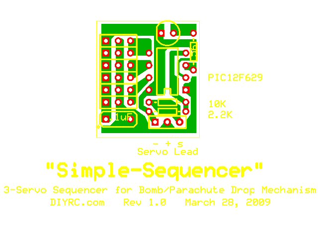
Design Criteria Summary:
1) Design a simple and affordable 3-servo sequencer
that is triggerable via a R/C signal (spare Rx channel), based around 8-pin PIC
2) Design so servo go from fully CCW to CW positions when triggered
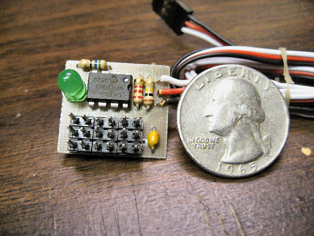
3) Lightweight and small in size
4) Simply plug&play operation... no programming
6) Works with most R/C receivers out there... PPM/PCM and 2.4GHz systems
8) Built-in failsafe operations (ignores invalid servo signal pulse)
Parts & Tools List
...
1) One
(1) PIC12F683 programmed with Servo Sequencer hex code
2) One 3pin x 6 row header for connecting to servos (3 outputs, 2
connections each)
3) One (1) 2.2K ohm Resistor
4) One (1) 10K ohm Resistor
5) One (1) 3-conductor Servo Wire (connect to spare channel on Rx)
6) One (1) 56 ohm resistor (for LED)
7) One (1) .1uF Capacitor (filtering)
9) One (1) Green 5mm LED
Building Instructions...
 BUILDING
INSTRUCTIONS FOR THE SIMPLE-TIMER KIT !
BUILDING
INSTRUCTIONS FOR THE SIMPLE-TIMER KIT !
Some pics:

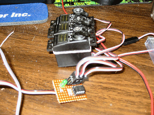
SORRY... NOT YET FOR SALE!
3-Servo Sequencer - (Assembled/Tested)
Programming Software...
THE PICAXE FIRMWARE FOR THIS PROJECT IS NOT FOR SALE ....
SORRY
 Pre-programmed
Picaxe chips are now available !
Pre-programmed
Picaxe chips are now available !
Click here to purchase
one now!
Testing and Operation Instructions...
(Online User's Manual)
The 3-Servo Sequencer designed by DIYRC.com is s small, light-weight servo
controller that has 3 servo outputs. The PCB allows for two servos to be
connected to each of the 3 servo output channels. The controller is
typically powered up using the same voltgae as that of your Radio Control (R/C)
receiver, typically 5-6 volts. Do not try to operate the controller at
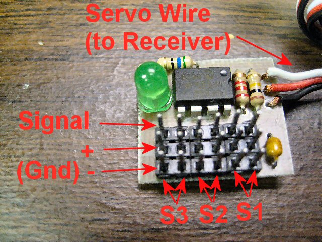
voltages higher than 6 volts as this will ruin the PIC. The picture to the
right indicates the inputs and outputs. Please pay particular attention to
the polarity of both the servo plug you plug into your receiver and also the
three servo connector ports.
Connecting your Servos
Servo ports #1 through #3 are shown in the picture above.
You can connect two servos to each of the 3 ports, just be certain to connect
your servos properly (ground/black wires towards edge of PCB). Be sure
your servo wires are pushed on the pins completely.
Connecting the controller to a spare channel on your R/C
Receiver
The controller has one servo wire extending from the PCB and this
wire is connected to a spare channel on your R/C receiver (for power & control).
Be sure to properly connect this paying attention to polarity (black lead is
ground). Connecting the controller backwards can ruin the PIC. The
spare channel on your receiver must be controllable from your transmitter in
order for the sequencer to operate properly. If you are using a programmable
transmitter, this channel should be set for full servo range (1ms-2ms
minimally). Typically, this spare channel is operated using a switch on
your transmitter (normally the switch in one directions gives you 1ms and switch
in other direction gives you 2ms pulsed servo signal). This servo signal is used
by the sequencer in order to trigger the step sequencer.
Operation of the 3-Servo Sequencer
Operation of the controller is pretty basic and controls the servo so they are
either in their fully Counter Clockwise (CCW) or Clockwise (CW) posisiton.
The controller has 4 sequences:
| SEQUENCE # |
SERVO CONTROL |
| 1 |
All Servos CCW |
| 2 |
Servo#1 is CW, #2 & #3 are CCW |
| 3 |
Servo#1 & #2 are CW, Servo#3 is
CCW |
| 4 |
All Servos are CW |
After sequence #4, if the controller is triggered again, it repeats to sequence
#1 and this process repeats indefinitely until power is removed.
Upon plugging in the controller (powering up), the controller first positions
all servos in a fully CCW position (Sequence#1). Normally, you would see the
green LED flash briefly and go out. If after powering up the sequencer,
you notice that the LED is lit continuously, this indicates that the sequence
trigger (transmitter's switch) is in its ON position. Simply move the
corresponding switch on the transmitter such that this LED goes off (indicating
OFF position... if you want to change this OFF position, simply reverse that R/C
channel using your computerized R/C transmitter). To make the sequencer
move to the next sequence, you then simply toggle the switch, moving the TX
switch from OFF to ON (LED lights), then back to OFF (LED goes off). After
doing so, you should see servo#1 go from fully CCW to a fully CW position (other
2 servos stay in CCW position). Next time you toggle the switch (On then
Off), it will step the sequencer to the next sequence (#2, both Servo #1 and #2
are now in CW positions while servo #3 is still in CWW position).
Triggering the sequencer another time (On then OFF) will them make servo#3 go to
fully CW position (just like servos #1 and #2). And finally, if you
trigger one more time (ON then OFF), the sequencer repeats back to sequence #1,
resetting all three servo channels to fully CCW positions. This step sequencer
repeats indefinitely until power is removed. If the sequencer senses an
invalid servo signal (< .75ms or >2.25ms), the sequencer ignores the signal and
does not step the sequencer.
I plan to add more information re: this neat gadget
as time allows.
 TWO
OF THESE UNITS ARE BUILT AND ARE CURRENTLY BEING BETA TESTED !!!
TWO
OF THESE UNITS ARE BUILT AND ARE CURRENTLY BEING BETA TESTED !!!
3-Servo Sequencer FAQ
Q1. .
A1. ...
 |
TBD
|
|
TBD |
**** VERY LIMITED
QUANTITIES ARE AVAILABLE ****
Click Here to visit the


Earthmen
Productions
© Dec-00-Mar-12
