Note: All pictures that follow
are
"clickable". Clicking on them will show you an enlargement!
WHAT ARE LEDs?
LED Characteristics
 LED
(Light Emitting
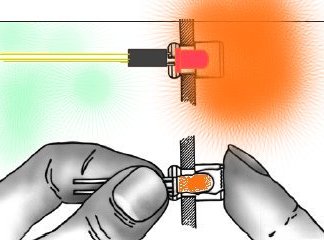
Diode) lights are electronic diodes that
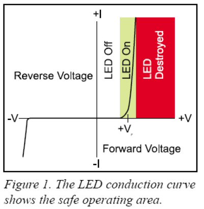
produce visible light. The light is produced only when current passes through the diode
in the forward direction,
propelled by a forward voltage charge (see figure
1). Before light is produced, however, the forward voltage across the diode must
be higher than the internal barrier voltage of the diode. This point, labeled +VF
(VoltageForward)
on the graph in figure 1, is the point at which the diode begins to conduct and
produces light. It is important to notice that once the voltage across the LED
reaches +VF
the diode conducts current extremely well. This
action is shown by the sharp rise in the forward current (+I) indicated by the
near vertical line on the conduction graph. The LED attempts to clamp the
LED
(Light Emitting
Diode) lights are electronic diodes that
produce visible light. The light is produced only when current passes through the diode
in the forward direction,
propelled by a forward voltage charge (see figure
1). Before light is produced, however, the forward voltage across the diode must
be higher than the internal barrier voltage of the diode. This point, labeled +VF
(VoltageForward)
on the graph in figure 1, is the point at which the diode begins to conduct and
produces light. It is important to notice that once the voltage across the LED
reaches +VF
the diode conducts current extremely well. This
action is shown by the sharp rise in the forward current (+I) indicated by the
near vertical line on the conduction graph. The LED attempts to clamp the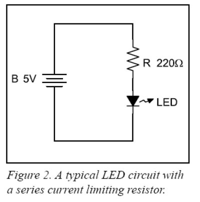 voltage near +VF
and can be easily destroyed by an excess of voltage. To protect the LED, a series current limiting resistor should be added, as shown
in figure 2, to the right.
The value of the series limiting resistor must
be calculated based on the maximum allowed LED current and the difference
between the applied voltage and the LED’s voltage
drop, +VF. Like any other diode, LEDs pass c
voltage near +VF
and can be easily destroyed by an excess of voltage. To protect the LED, a series current limiting resistor should be added, as shown
in figure 2, to the right.
The value of the series limiting resistor must
be calculated based on the maximum allowed LED current and the difference
between the applied voltage and the LED’s voltage
drop, +VF. Like any other diode, LEDs pass c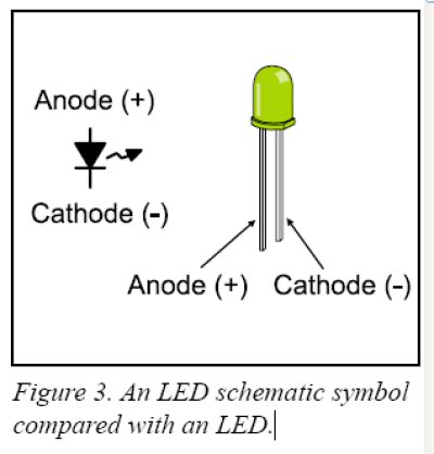 urrent
in the forward direction, but block current in the reverse direction (see figure
1). What this means is that the LED will only light up if connected with its
cathode on the negative side of the circuit, and its anode on the positive side
of the circuit. Too much reverse voltage will also destroy LEDs and diodes. The
cathode side of an LED is usually marked with a flat spot on the flange that
rings the body of the diode. The cathode wire is also usually shorter that the
anode wire of an LED. Figure 3, to the left, compares an LED with its schematic
symbol.
urrent
in the forward direction, but block current in the reverse direction (see figure
1). What this means is that the LED will only light up if connected with its
cathode on the negative side of the circuit, and its anode on the positive side
of the circuit. Too much reverse voltage will also destroy LEDs and diodes. The
cathode side of an LED is usually marked with a flat spot on the flange that
rings the body of the diode. The cathode wire is also usually shorter that the
anode wire of an LED. Figure 3, to the left, compares an LED with its schematic
symbol.
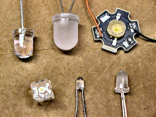 Note that LEDs come in various sizes
and brightness (often referred to milli-lumens or Lumens for
brighter LEDs). Sizes range from 3mm to10mm, and some even come in larger
(higher wattage)
sizes such as the 1 watt and 5 watt Luxeon style LEDs (shown on right). All LEDs have their own
Note that LEDs come in various sizes
and brightness (often referred to milli-lumens or Lumens for
brighter LEDs). Sizes range from 3mm to10mm, and some even come in larger
(higher wattage)
sizes such as the 1 watt and 5 watt Luxeon style LEDs (shown on right). All LEDs have their own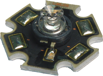 specific forward voltage so be sure to
calculate the proper series resistor
using this specification. LEDs come in various packaging too, as some emitters
are tightly focused (10-30 degree viewing angle, shown above in figure 3) while some are
designed for wider dispersion (360 degree viewable, as is the case for the
Luxeon Side Emitter shown on the right). You might also come across LED that have the
series resistor built into the LED itself! Although uncommon, these are
normally configured so you can easily connect them directly to either a 5v or 12v power
source.
specific forward voltage so be sure to
calculate the proper series resistor
using this specification. LEDs come in various packaging too, as some emitters
are tightly focused (10-30 degree viewing angle, shown above in figure 3) while some are
designed for wider dispersion (360 degree viewable, as is the case for the
Luxeon Side Emitter shown on the right). You might also come across LED that have the
series resistor built into the LED itself! Although uncommon, these are
normally configured so you can easily connect them directly to either a 5v or 12v power
source.
WHY A
SERIES RESISTOR?
Calculating the Series Current Limiting Resistor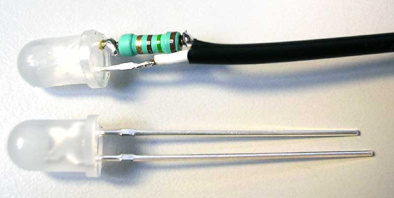
We know from figure 1, and the previous discussion above, that a series
current limiting resistor is required to prevent excessive current from
destroying the LED. But, how do you know how much current is too much? A rule of
thumb is that the maximum safe current for most 5mm LEDs is 20 milliamps (mA). Figure 2 shows a
typical electrical schematic with a series current limiting resistor in circuit
with the LED. This circuit is a voltage divider in which the diode voltage and
the resistor voltage must add up to the total applied voltage. As long as the
applied voltage exceeds the +VF
of the LED the voltage across the LED remains fairly
constant (see figure 1, again). A good digital multi-meter with a diode test
function will let you easily find the forward voltage of the LED. Once you know
the voltage across the LED, you also know that the voltage across the resistor
is the difference between the applied voltage and the LED forward voltage. The
calculations, below, demonstrate how to find the series
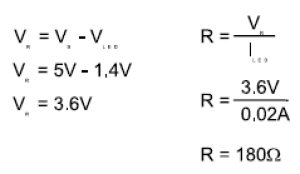 resistor
voltage. Once you know the resistor voltage and the maximum diode current, Ohm’s
Law lets you easily determine the size of the current limiting resistor. We’ll
assume that the LED forward voltage drop is 1.4 Volts. First, we determined that
the resistor voltage would be 3.6 Volts. Next, Ohm’s Law lets us calculate that
a 180W (ohm)
resistor will limit the current to .02 amps or 20 milli-amps (mA). If you can’t easily find a 180W
resistor, round up to the next commonly available size (figure 2 shows a 220W
resistor). Rounding up errs on the side of caution, increasing the circuit
resistance and decreasing the LED current. Although the LED may not be quite as
bright as with the calculated resistance, you will not have to worry about
damaging it with excess current.
resistor
voltage. Once you know the resistor voltage and the maximum diode current, Ohm’s
Law lets you easily determine the size of the current limiting resistor. We’ll
assume that the LED forward voltage drop is 1.4 Volts. First, we determined that
the resistor voltage would be 3.6 Volts. Next, Ohm’s Law lets us calculate that
a 180W (ohm)
resistor will limit the current to .02 amps or 20 milli-amps (mA). If you can’t easily find a 180W
resistor, round up to the next commonly available size (figure 2 shows a 220W
resistor). Rounding up errs on the side of caution, increasing the circuit
resistance and decreasing the LED current. Although the LED may not be quite as
bright as with the calculated resistance, you will not have to worry about
damaging it with excess current.
Note: You should also consider the wattage this resistor needs to be in
order to properly dissipate the excess current flowing through it. In the
example above, current of 20mA flowing through a 220W
resistor lends approximately 88mW or .088 watts (Power or Wattage = I2*R,
or .02 x .02 x 220 = .088). So in this case, a 1/8 watt (.125 watts), 220W
resistor would suffice. Most of the series resistor calculators below
(link) should also calculate the required series resistor value, ohms and
wattage.
Driving LEDs using a
Microcontroller
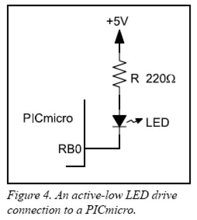 Transistor-Transistor
Logic (TTL) gates, like the 7400 family, are better at sinking current than sourcing
current. What this means is that the output transistors of a TTL device work
better when they connect a load to ground (0V) rather than to the +5V supply.
The circuit in figure 4, below, shows a TTL-like drive configuration in
Transistor-Transistor
Logic (TTL) gates, like the 7400 family, are better at sinking current than sourcing
current. What this means is that the output transistors of a TTL device work
better when they connect a load to ground (0V) rather than to the +5V supply.
The circuit in figure 4, below, shows a TTL-like drive configuration in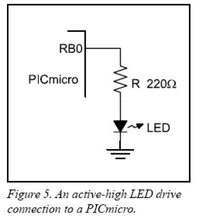 which a microcontroller I/O pin must be cleared (logic 0, or 0V output) to turn on the
LED. Microcontrollers are constructed of Complimentary Metal-Oxide Semiconductor
(CMOS) transistors as opposed to
TTL transistor. CMOS circuits work equally well when connecting an output device
to the high voltage side (+5V) as they do when connecting to the low voltage
side (see figure 5).
The advantage of an active high drive circuit like
that the one in figure 5, is that it’s easier for a programmer to follow the
logic that lights the LED. Making the microcontroller's output 1, or a high voltage,
turns the LED on. Making the output 0, or a low voltage, turns the LED off.
which a microcontroller I/O pin must be cleared (logic 0, or 0V output) to turn on the
LED. Microcontrollers are constructed of Complimentary Metal-Oxide Semiconductor
(CMOS) transistors as opposed to
TTL transistor. CMOS circuits work equally well when connecting an output device
to the high voltage side (+5V) as they do when connecting to the low voltage
side (see figure 5).
The advantage of an active high drive circuit like
that the one in figure 5, is that it’s easier for a programmer to follow the
logic that lights the LED. Making the microcontroller's output 1, or a high voltage,
turns the LED on. Making the output 0, or a low voltage, turns the LED off.
So, there you have it, a somewhat brief
tutorial on what LEDs are, why you need to use a current limiting resistor, and
how to properly drive an LED using a microcontroller. Also, be sure to not
overdrive the output of the PIC (PICs can sink around 25mA max). Typically, a microcontroller
(i.e. PIC) output can only drive one standard 5mm LED. If you need to
drive loads that require more current (>20-25mA), then use either a transistor
or a MOSFET/switch. The "Mini-Flash" LED controller uses four
(4) PN2222A
transistors, and are capable of driving around 600mA each (numerous LEDs).
The Mini-Beacon rotating beacon simulator uses one PN2222A transistor as an
output driver and can drive up to one 1 watt, 350mA Luxeon (600mA max.).
NOTE ABOUT FLASHING LEDS!
Because flashing LEDs only draw significant current momentarily
(i.e. duty-cycling),
you can often drive them harder, and in some cases, you can drive them without
the series resistor! This omission of the series limiting resistor only
applies to fast/brief flashing LEDs (i.e. strobe).
ASSEMBLING YOUR
LEDS
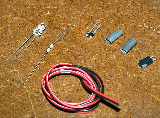
(Recipe: LED, series resistor, wire, connectors, heat shrink tubing
and some patience)
 There
are many ways to build LED assemblies. Typically, people mount LEDs in
their R/C models using either a primitive method (super-glue or hot-met-glue the
LED in model) or some clean installation method (such as plastic or metal LED
holders and/or lenses). Depending on what you plan to power the LEDs from,
you will need to attach a proper connector to the other end of the LED wire
(such as the case with the Mini-Flash and Mini-Beacon controllers). If you
are simply wiring up one LED to a controller, you will need the items pictured
to the left (LED, resistor, wire, connectors and heat shrink tubing.
There
are many ways to build LED assemblies. Typically, people mount LEDs in
their R/C models using either a primitive method (super-glue or hot-met-glue the
LED in model) or some clean installation method (such as plastic or metal LED
holders and/or lenses). Depending on what you plan to power the LEDs from,
you will need to attach a proper connector to the other end of the LED wire
(such as the case with the Mini-Flash and Mini-Beacon controllers). If you
are simply wiring up one LED to a controller, you will need the items pictured
to the left (LED, resistor, wire, connectors and heat shrink tubing.
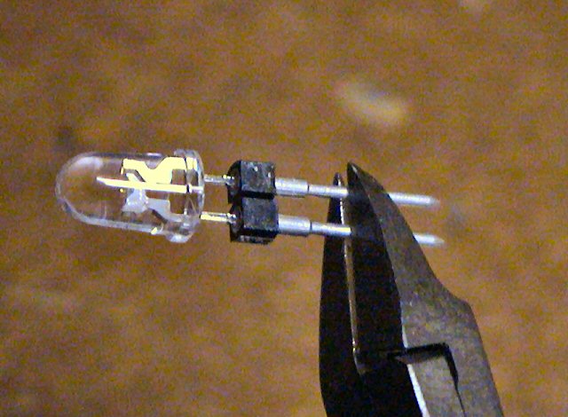
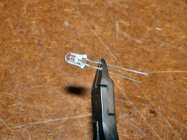 The
assembly begins with the shortening of the LED leads. Snip off both leads
approximately 1/2" from the LED base.
The
assembly begins with the shortening of the LED leads. Snip off both leads
approximately 1/2" from the LED base.
Note: Depending on how you plan to mount the LED, some mounting
areas might be limited in that the LED leads and resistor might not fit.
In this case, you can bend both leads 90 degrees, then snip to length before
soldering on the resistor and/or connectors.
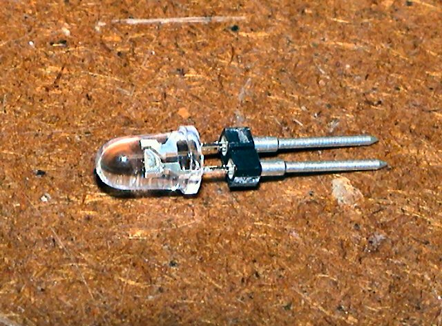 This
allows for plenty of lead to be inserted into an LED holder.
This
allows for plenty of lead to be inserted into an LED holder.
The LED holder (2-pin machine pin female connector) shown is not
required but cool if you ever want to change-out the LED to a different color or
simply replace it).
 If
using one of DIYRC.com's LED machine-pin holders, you would then also shorten
the leads of the connector before soldering onto them.
If
using one of DIYRC.com's LED machine-pin holders, you would then also shorten
the leads of the connector before soldering onto them.
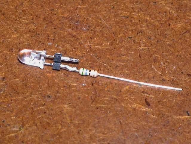 Next,
you would snip one of the resistor's leads (leave 1/4" long) and solder the
current limiting resistor to either of the LED/LED holder leads. For
this particular LED, a 56 ohm resistor is used to limit the current to 20-25mA, It
does not matter which LED lead you connect the resistor to but for
consistency, I normally solder the resistor to the Anode lead. Another
method to determine the Anode and Cathode leads is to look closely inside the clear LEDs. The lead that
connects to the "emitter holder" (looks like a cup) is the Cathode while the
lead that connects to a very fine wire that leads to the top of the emitter is
the Anode).
Next,
you would snip one of the resistor's leads (leave 1/4" long) and solder the
current limiting resistor to either of the LED/LED holder leads. For
this particular LED, a 56 ohm resistor is used to limit the current to 20-25mA, It
does not matter which LED lead you connect the resistor to but for
consistency, I normally solder the resistor to the Anode lead. Another
method to determine the Anode and Cathode leads is to look closely inside the clear LEDs. The lead that
connects to the "emitter holder" (looks like a cup) is the Cathode while the
lead that connects to a very fine wire that leads to the top of the emitter is
the Anode).
 Next,
snip the other end of the resistor so only 1/4" is left.
Next,
snip the other end of the resistor so only 1/4" is left.
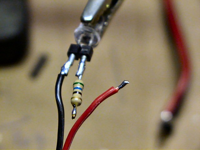
Strip the black (ground) lead on one end of the 2-conductor wire (1/8"
approximately), and tin the wire. Solder the tinned black wire to the LED
pin without the resistor (in this case, the cathode or negative lead on the
connector/LED).
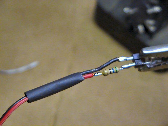
 After
attaching the black lead, measure the red wire and shorten so it lines up with
the end of the resistor. Strip, tin and solder the red lead to the open
end of the resistor. Your LED connections are made!
After
attaching the black lead, measure the red wire and shorten so it lines up with
the end of the resistor. Strip, tin and solder the red lead to the open
end of the resistor. Your LED connections are made!
Note: If you are soldering directly to the LED leads, try to use just
enough heat to properly solder the wire & resistor leads. The less heat,
the safer for the LED.
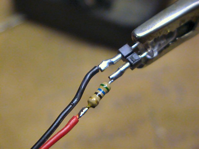
Next, slide a piece of 3/16" heat shrink tubing over the other end of the LED
wire and slide it down the length of the wire so it covers the LED's wires,
resistor and connections. Because the connection of the red wire is offset
from that of the black, you can easily heat-shrink the entire assembly without
the possibility of short circuits.
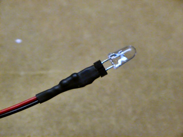
This is what the completed LED assembly should look like. If you are not
using an LED holder like that shown, the shrink tubing would cover the LED leads
entirely, but should not cover the base of the LED (else, the LED will not fit
any of the designed holders)
This completes the connection on that end of the LED wire!
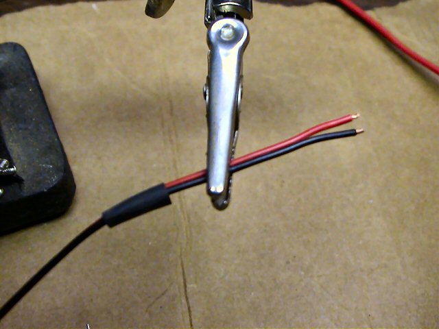
Note: Before beginning the connections on the other side of the LED wire, it is
important to slide on the piece of 3/16" heat-shrink tubing needed to eventually cover
the connector you will install next.
Once you solder connectors onto this wire, you will not be able to slide the
heat-shrink tubing over the connector assembly.
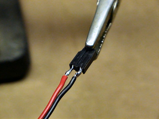
Next, solder the proper connector onto the two LED wires (red/black). It
is not important as to which wire to connect to which connector pin.
The connector shown here is similar to those supplied with both the Mini-Flash
and Mini-Beacon controller (/1" spacing, 2-pin female connector, similar
to a servo connector but with only two pins vice three)
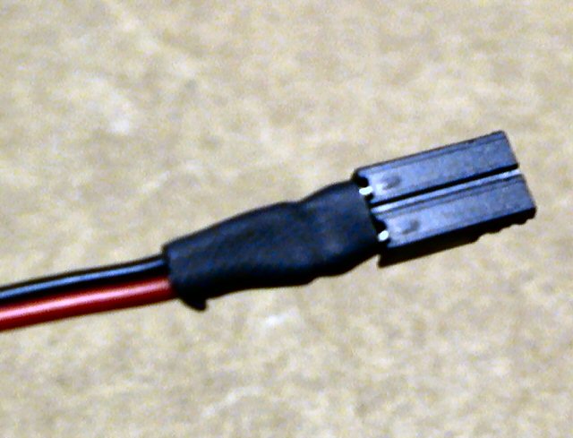
Next, slide the heat-shrink tubing over these connectors and shrink so it only
covers the connector's pins, not the actual connect itself.
If the tubing goes over the connector, you will not be able to connect these
side-by-side on the Mini-Flash controller.
Note: If you want, you can also connect the resistor to one of these
connector leads instead of one of the LED leads.
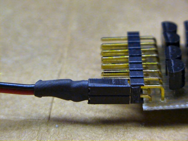
The picture to the left shows how this completed LED connector would connect to
one of the Mini-Flash output connectors (right angles 2 row by 8 pin header)
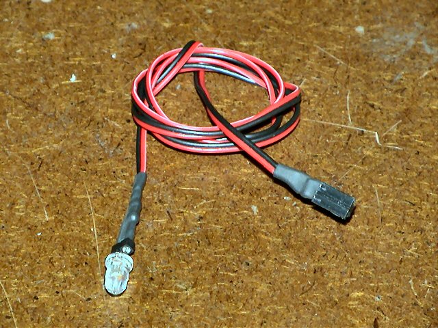
So, here's the completed LED assembly...
...LED with series resistor connected to one end of the LED wire, while the
other end of the LED wire is connected to a mating connector that plugs into the
Mini-Flash or Mini-Beacon LED controller.
MOUNTING YOUR LEDS ON YOUR MODEL
LED MOUNTING TECHNIQUES - LENS, LED HOLDERS, ETC...
Note:
DIYRC.com sells not only
LEDs, but also
LED holders and lens.
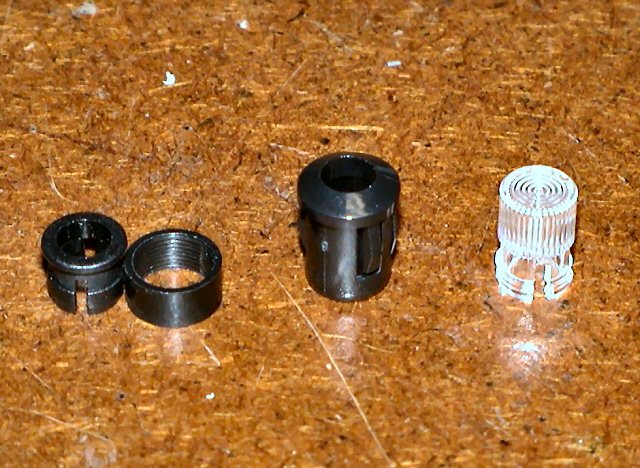
There are plenty of ways to mount LEDs in models. On the left are three
(3) types of LED connectors which DIYRC.com sells.
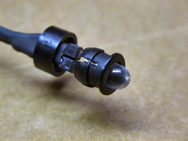
The one to the left is a
2 piece 5mm LED holder (typical). The one in the
middle is a
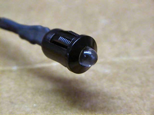
one piece, heavy-duty" 5mm "snap-in" LED holder (snap LED into it,
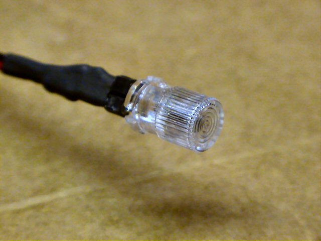
then snap this into a 5/16" hole). The one to the right is a
clear fresnel
lens that acts like an LED holder too (snap LED into it, then snap this assembly
into a 1/4" hole)
Below are a few picture that show how an LED would look in one of these holders
(Clear Fresnel Lens, 2-peice black plastic holder, and the 1 piece black plastic
heavy-duty holder)
TYPICAL LED SETUP ON AIRPLANES, HELICOPTERS AND BOATS!
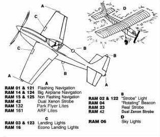
Click one of the links below to view some ideas as to how and where to
mount LEDs on R/C models.
RECOMMENDED LOCATION OF LEDS FOR VARIOUS R/C MODELS
|
Facts
on setting up scale airplane lighting to FAA specs!
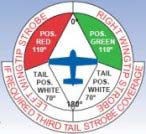
AIRCRAFT LIGHTS: An Explanation
The Federal Aviation Administration (FAA) require that aircraft have
position or navigational lights configured in the same manner.
POSITION LIGHTS (Red [L], Green [R], & White [Rear side of Tail] *all
solid*)
As the pilot faces forward in the cockpit, he would find a green light on
his right wing tip, a red light on his left wing tip and a white light on
the tail. These position lights are required to be on for all operations,
ground and flight, between the hours of official sunset and sunrise.
ANTI-COLLISION LIGHTS (Red or White or one of each) Strobe, Flashing,
or rotating)
Anti-collision lights are used primarily to assist in assuring that an
aircraft is readily seen while on the ground or in flight. These lights are
generally mounted in the wing tips not far from the position lights or **on
the TOP of the Vertical Fin**. With most airline operated aircraft
these lights are white and are generally of the strobe variety. Another type
of anticollision light is red, (strobe, flashing, oscillating or rotating
beacon type) and is located on top and/or underneath the fuselage (main body
structure) of the aircraft. These lights are generally on for all
operations, ground and flight, day and night, below 18,000 feet. At night
these lights are kept on regardless of altitude.
LANDING LIGHTS
The aircraft landing lights are used for both illumination of the
landing/take-off area as well as for collision avoidance in flight. Landing
lights, depending on the size and type of aircraft, can be mounted in a
number of locations. They can be located in the left and right leading edge
of the wings, on the nose gear strut, or in some cases are extended below
the wings.
RUNWAY TURNOFF LIGHTS
Runway turnoff lights, sometimes referred to as taxi lights, visually assist
the pilot at night when maneuvering between the terminal and the runway.
These lights are either mounted on the leading edge of the wings, on the
nose gear strut or some location which will provide sufficient illumination
in front of the aircraft. These lights are rarely operated while the
aircraft is in flight unless they are an integral part of the landing light
system or unless the pilot deems it necessary for safety reasons (i.e.
additional collision avoidance).
Original Text Here:
http://www.textfiles.com/ufo/UFOBBS/1000/1579.ufo
or
http://www.FAA.gov
More good info can be found here:
 http://www.creativair.com/source/_inst/requirements.pdf http://www.creativair.com/source/_inst/requirements.pdf
|
Other Notes
DON'T FORGET THE ALL IMPORTANT
SERIES RESISTOR INLINE WITH ALL LEDS !!!
WHY THIS SERIES RESISTOR?
READ BY CLICKING HERE!
The LEDs you will connect to the
MINI-FLASH need to have a resistor in series with one of the LED's leads
in order to limit the current going into the LEDs (I usually use the + anode lead
but you can use either the anode or cathode lead). The
resistor value depends on the LED's forward voltage and the LED's maximum
current rating. These specs are usually supplied by the LED manufacturer.
The basic formula for calculating this required series LED resistance is as
follows:
Required Resistance = (Voltage
Source - LED Forward Voltage) / Max LED Current
or
R = (Vs-Vf) / Imax
As an example, a particular LED has a 3.0 volt
forward voltage (Vf) and a maximum current rating of 20mA. It is to be
driven with a 5.0 volt source. Therefore,
R = (5.0 - 3.0) / .020
or R = 2.0 / .020
or
R = 100 Ohms
If you do not know
the LED specs, typically, a 80-100 ohm resistor will do just fine.
CLICK HERE FOR MORE ON-LINE
LED CURRENT LIMITING RESISTOR CALCULATORS & FORMULAS!
Q1. How do you compensate for
differing forward voltages and current drawn by differing LED's?
A1. Ah.... good question....
The input voltage to LEDs is all not that important (usually 5v is fine for
all). It is the current that you push through the LED that is important, as you
do not want to drive them with too much current. You usually always need to put
a series resistor inline with one of the LED leads such to limit the current. I
use a neat calculator, I even have a link for it on my webpages.
You really need to know the specs on the LEDs, particularly the LEDs rated
current (typical 5mm LEDs run around 20-25 milliamps).
Here's a few calculators you can use.
You simply enter the supply voltage (in the
controller's case, 5 volts), the LEDs forward voltage (this varies from LED to
LED) then enter the rated LED current (typically 20-25 milliamps). Then hit the
"find R" button and the program calculates the resistor value you need for that
LED (typically a 68 - 120 ohm resistor is required). Be careful also as there
exists some LED that already have the series resistor incorporated in the LED
(not all that common though). Once the resistor value is determined, I
usually then solder it to the end of one of the LED leads. The wires then
leading from this LED assembly is then connected directly to the controller
using a miniature machine-pin female socket (I will provide at least 8 with
every controller). Putting the series resistors on the PCB would take up
space (unless they were SMD maybe).

Earthmen
Productions
© Dec-00-Mar-12

Home | Mini-Flash Flasher | Mini-Beacon Flasher | Maxi-Flash | Easy-Flash | Pro-Flash Flasher | LED Assembly | LED Calculators
 AIRPLANES
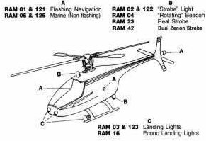 HELICOPTERS
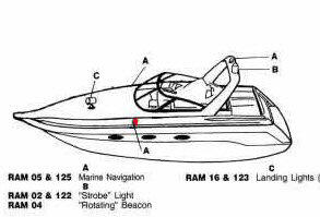 BOATS
BOATS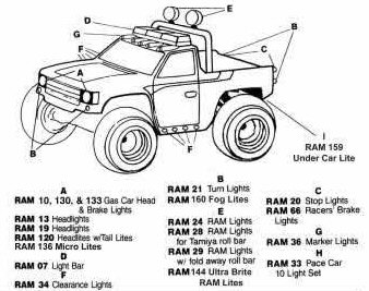 CARS/TRUCKS