Note: All
pictures that follow are "clickable"
See the Mini-Flash installed in a TRAXXAS Revo R/C Truck
!
 See
the Mini-Flash installed in a Scale R/C Heli !
See
the Mini-Flash installed in a Scale R/C Heli !
Another cool Heli Video is HERE
(uses two Mini-Flash controllers)
CLICK HERE TO SEE MORE CUSTOMER PROJECTS!
Assembly Instructions
User's Manual-Download
or View
BUY ONE NOW!
A lil' history ...
 This
project, called "Mini-Flash", is a miniature
programmable LED Sequencer/Flasher that is based around the PIC microcontroller. The Mini-Flash
is a PC-programmable, 4 LED channels sequencer that also incorporates Radio
Control (R/C) functions. These functions allow the Mini-Flash to be used
for scale, navigation lighting and even night-time flying! The user at any
time can reprogram the LED sequencer using a
PC-based (i.e. Windows)
This
project, called "Mini-Flash", is a miniature
programmable LED Sequencer/Flasher that is based around the PIC microcontroller. The Mini-Flash
is a PC-programmable, 4 LED channels sequencer that also incorporates Radio
Control (R/C) functions. These functions allow the Mini-Flash to be used
for scale, navigation lighting and even night-time flying! The user at any
time can reprogram the LED sequencer using a
PC-based (i.e. Windows)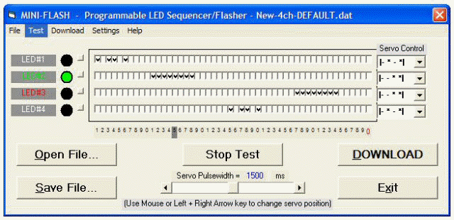 program that includes a unique and intuitive
Graphical User Interface. In fact, the servo lead which is
normally plugged into a spare R/C receiver channel for control, is
also used to reprogram the Mini-Flash flasher/sequencer via PC's USB
port/connection. A
newly designed USB programming cable
coupled with the free downloadable
programming software allows the user to program the Mini-Flash.
The software also runs stand-alone, allowing the user to "test" the LED sequence
they develop by use of software-based graphical representations of the 4
LED channels. The sequence speed can also be programmed by the
user. Each sequence contains 50 events and each of the 4 LED
channels can be either ON or OFF for every events. If the user
wants to develop a sequence with fewer events, this can also easily be
programmed.
program that includes a unique and intuitive
Graphical User Interface. In fact, the servo lead which is
normally plugged into a spare R/C receiver channel for control, is
also used to reprogram the Mini-Flash flasher/sequencer via PC's USB
port/connection. A
newly designed USB programming cable
coupled with the free downloadable
programming software allows the user to program the Mini-Flash.
The software also runs stand-alone, allowing the user to "test" the LED sequence
they develop by use of software-based graphical representations of the 4
LED channels. The sequence speed can also be programmed by the
user. Each sequence contains 50 events and each of the 4 LED
channels can be either ON or OFF for every events. If the user
wants to develop a sequence with fewer events, this can also easily be
programmed.
 As if these are not enough features, the
"Mini-Flash" also includes
a control for each of the 4 channels that allows the user to use an R/C servo
output (from a R/C receiver) as a "switch" control for the 4 LED channels.
This feature allows the user to control (active or inactive) each of the 4
channels in regards to the position of the servo control input. If the
user uses a stick or slider for control input, the use will be able to program 1
of 4 "Zones"; 0-1/4 stick, 1/4-1/2 stick, 1/2-3/4 stick and 3/4-Full stick).
If the user uses a switch as the servo input, the user will be able to define
one of 2 "Zone" settings for each LED channel (either 0-1/4 and 3/4-Full).
As if these are not enough features, the
"Mini-Flash" also includes
a control for each of the 4 channels that allows the user to use an R/C servo
output (from a R/C receiver) as a "switch" control for the 4 LED channels.
This feature allows the user to control (active or inactive) each of the 4
channels in regards to the position of the servo control input. If the
user uses a stick or slider for control input, the use will be able to program 1
of 4 "Zones"; 0-1/4 stick, 1/4-1/2 stick, 1/2-3/4 stick and 3/4-Full stick).
If the user uses a switch as the servo input, the user will be able to define
one of 2 "Zone" settings for each LED channel (either 0-1/4 and 3/4-Full).
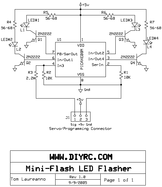
Design Criteria Summary:
1) Design a simply and cheap programmable LED
flasher around 8-pin PIC
2) Design so LED sequencing speed and sequence pattern is programmable
3) Lightweight and simple to build (DIY)
4) Power off of existing R/C servo connector
5) Use servo signal to vary how each LED channel responds (turn programmed
pattern on or off)
6) Design programming software so it's intuitive and provide varying functions
(PLEASE READ
SOFTWARE ISSUES/CONCERNS NOTE BY CLICKING THIS)
7) Interface to computer using RS-232 (9-pin) connector most computers have...
Can be used with most USB-to-Serial Converters (Click here to see
a list that works)
8) Programmable almost indefinitely... change your sequence pattern/speed many,
many times
9) Powers many LEDS (at least 600mA per channel... each typical 5mm LED uses
25-40mA)
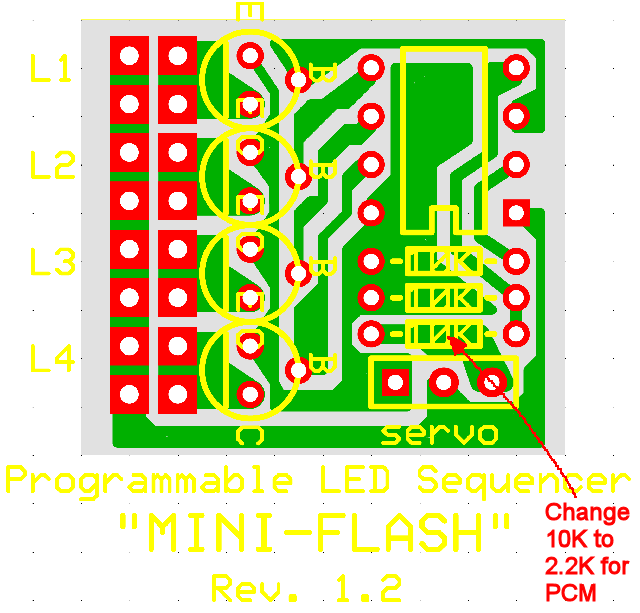
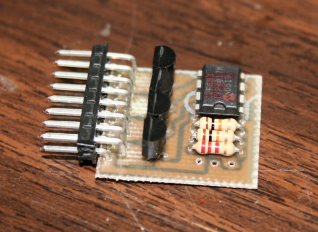
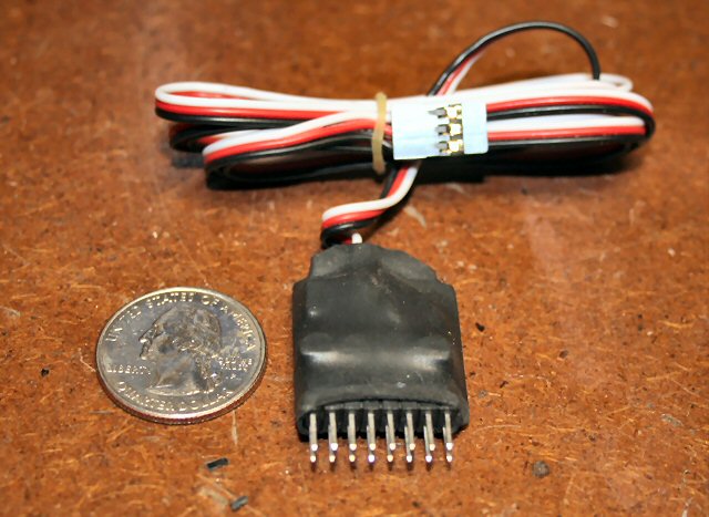
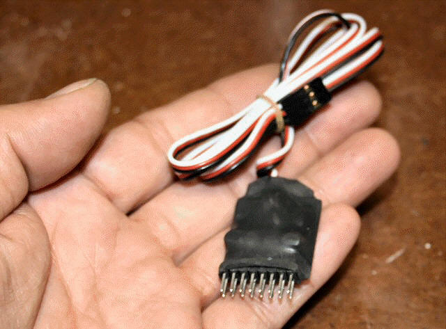
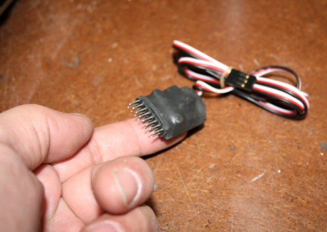
PLEASE NOTE: The Mini-Flash below is
now being built with a standard
dual-row .025" square header, similar to that used by Curtek Lighting systems.
You
can now easily plug in your Curtek LEDs or other assembled LEDs that use standard
two-pin servo-type female connectors. Although the machine pin
connectors I used in the past (shown above) were lighter and of higher quality,
they unfortunately have become expensive and availability has been sketchy.
WANT TO BUY A PRE-ASSEMBLED & TESTED
MINI-FLASH CONTROLLER?
Mini-Flash Controller and Programming Cable (+ 8
mating LED connectors)
(Assembled & Tested, LEDs and wire sold seperately)
CLICK HERE TO
BUY ONE NOW !
LIMITED SUPPLY !
Mini-Flash Controller -
Pre-Programmed PIC Only
(This is for one pre-programmed PIC only... no other
parts)

CLICK HERE TO BUY ONE NOW !
LIMITED SUPPLY !
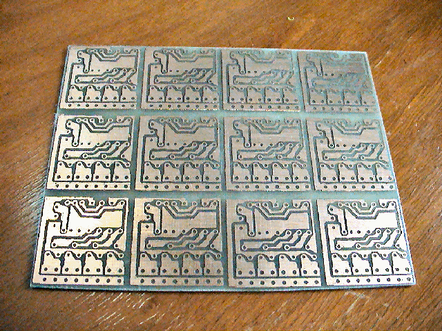
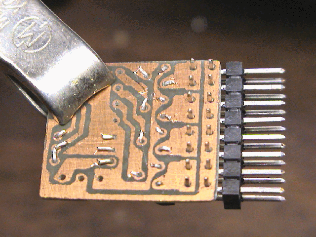
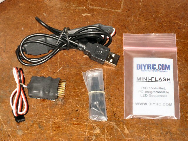
Parts & Tools List
...
1) One
(1) PIC12F683 Chip (preprogrammed with Mini-Flash code)
2) Three (3) 10K ohm resistors (2 for Mini-Flash, one for programming cable)
3) One (1) 2.2K resistor
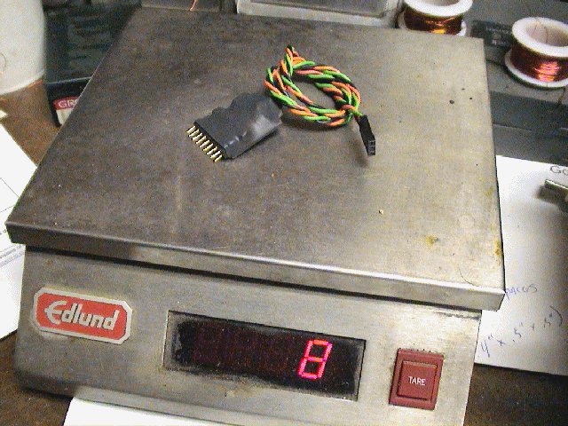
4) One (1) Servo Lead/Pigtail wire for Mini-Flash
5) One (1) 16 pin (8x2) Dual-Row header (male)
6) Four (4) 2N2222 or PN2222A NPN Transistors
7) One (1) RS-232 9-pin female connector (to connect to PC com port)
8) One (1) RS-232 9-pin Hood/Cover
9) One (1) Programming Cable Wire (i.e. Servo Extension)
10) One (1) Programming cable wire (2 conductor wire, 4' or so)
11) 8 dual-row headers (mating connectors for Mini-Flash Header)
12) 3 pieces of heat shrink tubing for assembly (for Mini-Flash & programming
cable)
(Note: Customer is
responsible for supplying LEDs and connecting wires...
LEDs are sold separately
in the DIYRC webstore... CLICK HERE!)
Building Instructions...
* MINI-FLASH BUILDING INSTRUCTIONS *
CLICK HERE TO VIEW THE BUILDING INSTRUCTIONS FOR THE MINI-FLASH
Programming Software...
THE PIC FIRMWARE CODE FOR THIS PROJECT
IS NOT FOR SALE .... SORRY

 DOWNLOAD THE MINI-FLASH PROGRAMMING
SOFTWARE (Rev 4)!
* Click Here to Download *
(CLICK HERE to view installation procedures)
(PLEASE READ SOFTWARE ISSUES/CONCERNS NOTE BY CLICKING
THIS LINK)
IF REV4 FAILS TO INSTALL, TRY INSTALLING REV3
(CLICK HERE!)
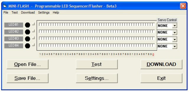
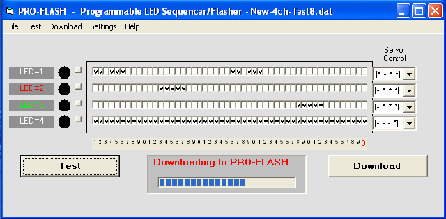
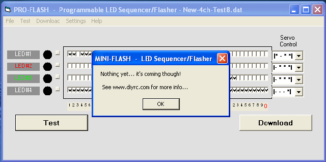
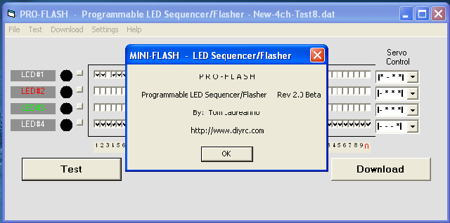
Screen shots of the Mini-Flash programming
software (Rev1). Rev4 has screen differences such as buttons and during download....
Main Screen
|
File Menu Screen
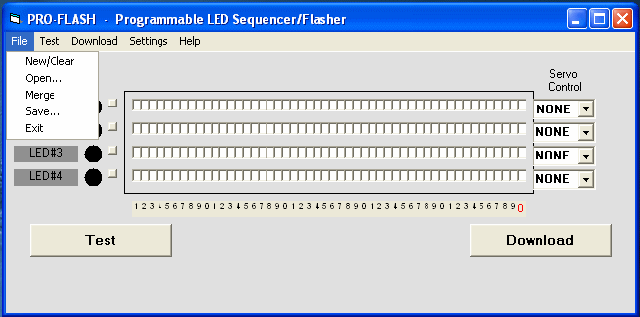 |
Download Screen #1
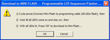 |
Download Screen #2
 |
Setup Menu (Comm port, Test speed, PIC
speed)
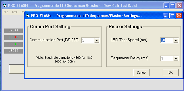 |
Help/About Screen
 |
Help/How-To Screen
 |
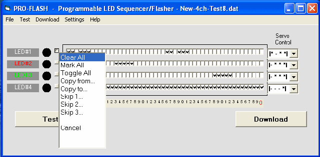
Channel Menu #1 (click on tiny square
button)
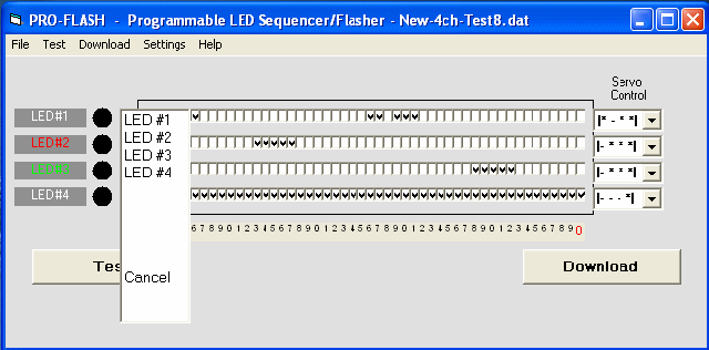
 |
Channel Menu #2
 |
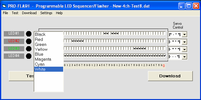
LED Color Menu (click on LED text)
 |
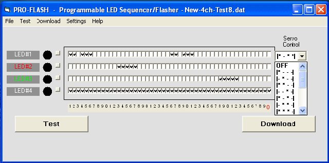
LED Servo Control Menu (select mask)
 |
Exit Screen
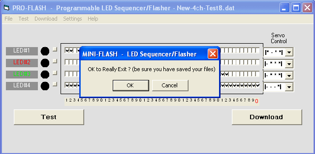 |
Testing and Operation Instructions...
*
MINI-FLASH USERS' MANUAL
*
CLICK HERE TO VIEW THE USERS'
MANUAL FOR THE MINI-FLASH
* MINI-FLASH USERS' MANUAL
(PDF)
*
CLICK HERE TO DOWNLOAD THE USERS'
MANUAL FOR THE MINI-FLASH
I plan to add more information re: this neat gadget
as time allows.
 If
600mA per channel is not enough fro your application, then check out the
"MAXI-FLASH". This is basically the same Mini-Flash controller but
instead of small transistor outputs, the Maxi-Flash controller has 4 high current switching MOSFET. The MOSFETs will use its own power source (i.e., not the
receiver's) to power high current loads such as Incandescent bulbs, winch
motors, and other electro-mechanical devices. This can be used to power glow plugs, high output LEDS,
incandescent lights, motors/pumps, bomb drops,
and other devices that require high power switching. Stay
tuned...
If
600mA per channel is not enough fro your application, then check out the
"MAXI-FLASH". This is basically the same Mini-Flash controller but
instead of small transistor outputs, the Maxi-Flash controller has 4 high current switching MOSFET. The MOSFETs will use its own power source (i.e., not the
receiver's) to power high current loads such as Incandescent bulbs, winch
motors, and other electro-mechanical devices. This can be used to power glow plugs, high output LEDS,
incandescent lights, motors/pumps, bomb drops,
and other devices that require high power switching. Stay
tuned...
MINI-FLASH Notes & FAQ
IMPORTANT!
: It is highly recommended
that you first install and test drive the Mini-Flash programming software before
making a purchase. Few customers have run into issues when trying to
install/run the software, often getting an error like that shown below:
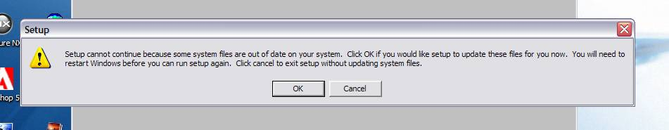
Click the OK button to attempt to
install the required files. If you still experience an error when trying
to run the software (different error that starts w/ a "&H"), the only
known fix to this MS issue is to install an MS Office product, such as one of
the two below:
1) Free
trail version of MS Office (link below):
http://us20.trymicrosoftoffice.com/default.aspx?culture=en-US
or better yet...
2)
Free
version of MS ActiveX Control Pad (link below):
http://download.microsoft.com/download/activexcontrolpad/install/4.0.0.950/win98mexp/en-us/setuppad.exe
This issue is caused by the MS
operating system accidentally deleting or not installing the proper DLL and/or
OCX files needed for Visual Basic distribution code to run properly (such
as the Mini-Flash software). Installing MS Office (any variant) seems to
install the required files... and mysteriously, the Mini-Flash software begins
working! Go figure! It has also been confirmed
recently that the Mini-Flash software still works OK even after uninstalling the
free ActiveX Control Pad software noted above! Cool!
Q1. How do you compensate for
differing forward voltages and current drawn by differing LED's?
A1. Ah.... good question....
The input voltage to LEDs is all not that important (usually 5v is fine for
all). It is the current that you push through the LED that is important, as you
do not want to drive them with too much current. You usually always need to put
a series resistor inline with one of the LED leads such to limit the current. I
use a neat calculator, I even have a link for it on my webpages. You really need
to know the specs on the LEDs, particularly the LEDs rated current (typical 5mm
LEDs run around 20-25 milliamps). Here's the calculator:
http://linear1.org/ckts/led.php
You simply enter the supply voltage (in the
controller's case, 5 volts), the LEDs forward voltage (this varies from LED to
LED) then enter the rated LED current (typically 20-25 milliamps). Then hit the
"find R" button and the program calculates the resistor value you need for that
LED (typically a 68-120 ohm resistor is required). Be careful also as there
exists some LED that already have the series resistor incorporated in the LED
(not all that common though). Once the resistor value is determined, I
usually then solder it to the end of one of the LED leads. The wires then
leading from this LED assembly is then connected directly to the controller
using a miniature machine-pin female socket (I will provide at least 8 with
every controller). Putting the series resistors on the PCB would take up
space (unless they were SMD maybe).
Q2. I have a question: So tell me
how you could control different sequences with a TX like a 6102 which is a 6
channel but the 2 extras are more like landing gear, and flaps?
A2. Great question.... ( I knew I'd eventually have
write about this, as most will probably use a switch and some will have the
luxury of having a spare variable channel, like a rotating knob or lever).
Is the landing gear channel on your system controlled by a switch ? (most
likely). How about the flaps, are these a switch too or is this a rotating knob
(like I think my Futaba 9C has) ??
If the channel you have the flasher plugged into is controlled (Tx) using a
toggle switch, you will still be able to control the 4 LED channels/sequences,
but you will only have two possible servo control positions, on (*---) and off
(---*). If you were to look at the "Servo Control" pull-down in the
software, you have 16 different "servo zone" combinations you can chose. All 16
work only when you are using a variable Rx channel, such as a channel being
controlled by a knob, slider or stick. If you are only using a "switched" Rx
channel and you want to simply use the switch to turn the channel on or off, you
would set up the "servo control" such that it is "*---". What this would do is
make the selected LED channel active only when the switch is in the down
position (actually, it is as if the stick is in the position, 0->1/4
deflection). Now catch this, if you were to choose the "**--" option or the
"***-" option, this would still have the same effect. When using a toggle
switch on your Tx to control the LED flasher, the receiver will never
output the middle two zones (-**-). Therefore selecting these zones in a
channel's servo zone will do nothing.
Q3. I do not have a RS-232 port
on my laptop/computer!
What can I do now?
A3. No Problem! You can use an USB-to-Serial
converter that plugs into a spare USB port on your computer. On the other
end of the cable is a female RS-232 connector you plug the Mini-Flash
programming cable into.
CLICK HERE TO VIEW A
LIST THAT IS KNOWN TO WORK !
Additional Notes...
NEW
USB MINI-FLASH PROGRAMMING CABLE!
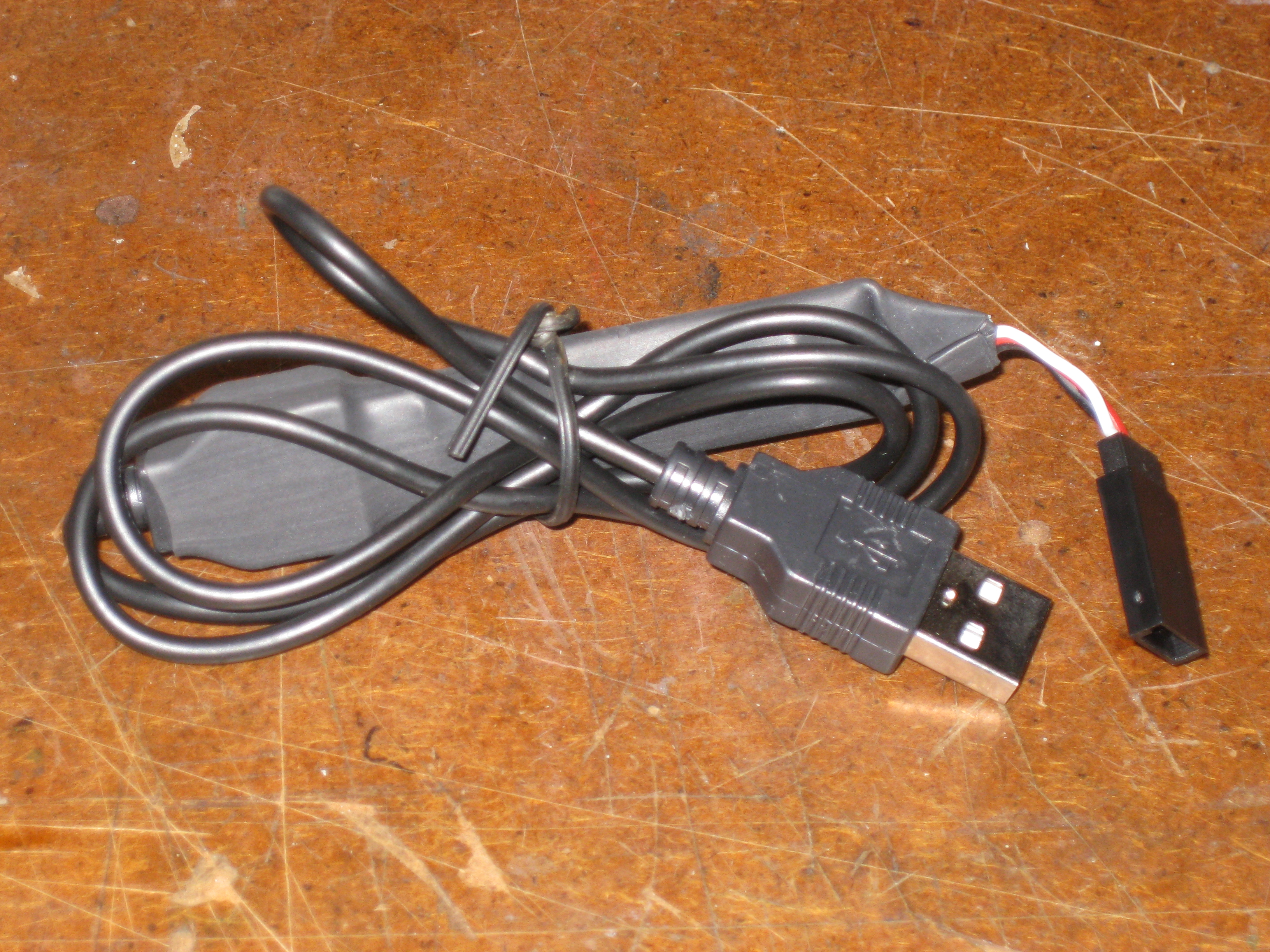 Recently, I finally got around to designing a new
Mini-Flash programming cable that is USB vice the older RS-232 serial (9-pin)
connector type. All of the Mini-Flash kits I sold in the past included a
serial cable and since most new computers do not even come with a serial port,
customers use to have to purchase a separate USB-to-Serial (RS232) converters
(some models noted below even). So, I built & tested a new USB programming
cable and even sold a few to some recent customers. So far, the feedback
is great. The only extra step customers have to do is install the USB
driver (supplied on disk or via downloading from this site (see below in notes)
before plugging in the new USB programming cable.
Recently, I finally got around to designing a new
Mini-Flash programming cable that is USB vice the older RS-232 serial (9-pin)
connector type. All of the Mini-Flash kits I sold in the past included a
serial cable and since most new computers do not even come with a serial port,
customers use to have to purchase a separate USB-to-Serial (RS232) converters
(some models noted below even). So, I built & tested a new USB programming
cable and even sold a few to some recent customers. So far, the feedback
is great. The only extra step customers have to do is install the USB
driver (supplied on disk or via downloading from this site (see below in notes)
before plugging in the new USB programming cable.
MINI-FLASH USB PROGRAMMING CABLE
NOTES!
The
new USB programming cable drivers and programming software can be downloaded from here
(it is included as part of the Rev4 Zip package you can download
using the link below):
http://www.diyrc.com/Mini-Flash-Rev4.zip
Download and
unzip/extract all files to a new directory of your choice
(preferably a new directory named MiniFlashRev4 or something like
that)
======================================================================
======================================================================
Installation Procedures (USB Driver & Mini-Flash Software)
======================================================================
======================================================================
1. Install USB Drivers (only for Mini-Flash USB programming cable,
not the older RS232 version)
INSTALLATION OF USB DRIVERS ON A WINDOWS Vista or 7 OPERATING SYSTEMS
=====================================================================
If you are installing on a Window 7 machine, follow these
instructions sent by a customer:
a) Plug in the Mini-Flash USB programming cable into a spare USB
port, you will probably here a ding or two...
b) After possibly a ding or two, you will see a message pop up
saying it can not find a driver...
c) Choose the option to search for one from a specified location...
d) Browse to the "USB Driver" directory on the disk/download and
then choose the "Win2K_XP" directory and press OK
e) The install should complete successfully, and a message could pop
up that says your hardware is ready to use.
If the Install procedure above do not appear to work, try these:
===============================================
(be sure you unplug the USB dongle before proceeding with the
procedures below)
a) Explore disk and double-click (open) the "USB Driver" Folder...
b) In this USB Driver folder, you should find a "SETUP" or INSTALL
file... double-click it to run the application (if more than one
Install/Setup file exists, choose the proper one for your computer
system, (Vista or XP/7)
c) Follow instructions and when completed, you should then plug in
your USB programming cable (not before)
d) You should hear your PC make a few ding sounds and software
should install automatically. Should a window pop up during install,
follow all direction, possibly having to search for the driver
software...
e) After complete installation, you should see a displayed message
that says your hardware is ready to use.
f) You should check your hardware settings (particularly the Comm
Port number which the Mini-Flash software settings need to program
the controller)...
g) To run the Device Manager, right-click on the My Computer icon on
your desktop and select "Properties"
h) From Properties, select the Hardware tab, then press the Device
Manager button
i) In this list of devices, you should see a category called
"Ports". In this category list you should see a new entry named "USB
Serial...". the COM number that follows in parenthesis is the
communications port number (usually 1-10) you will have to set in
the Mini-Flash programming software (under settings, see step b)
below)
2. INSTALL THE MINI-FLASH REV4 SOFTWARE & CONFIGURE SETUP SCREEN
(PORT#)
=========================================================================
a) Install Mini-Flash software by exploring the install disk's main
directory. Here you should see a SETUP.EXE file... simply
double-click on this setup file to install the Mini-Flash
programming software... follow all directions (typically clicking OK
using default settings). If during the install process it mentions
that your computer has newer files than those trying to be
installed... simply select to not over-write the current files. When
completed, you will not see a desktop icon but you will see the
Mini-Flash program under the START button (you could always
right-click on the Mini-Flash program under START to copy a shortcut
to your desktop)
b) IMPORTANT! Before using the Mini-Flash software to program a
Mini-Flash, be sure to configure the programming port# under the
SETUP screen in the software. This port number should be selected to
match that viewed in step i) above (Installation of USB Driver)