A lil' history ...
 As if we haven't seen enough Aiptek R/C switches, here is yet another, this time designed
around a PIC microcontroller.
Since the design is based upon a Flash PIC (PIC12F683), you
can continually download new code, allowing for experimentation and prototyping.
As if we haven't seen enough Aiptek R/C switches, here is yet another, this time designed
around a PIC microcontroller.
Since the design is based upon a Flash PIC (PIC12F683), you
can continually download new code, allowing for experimentation and prototyping.
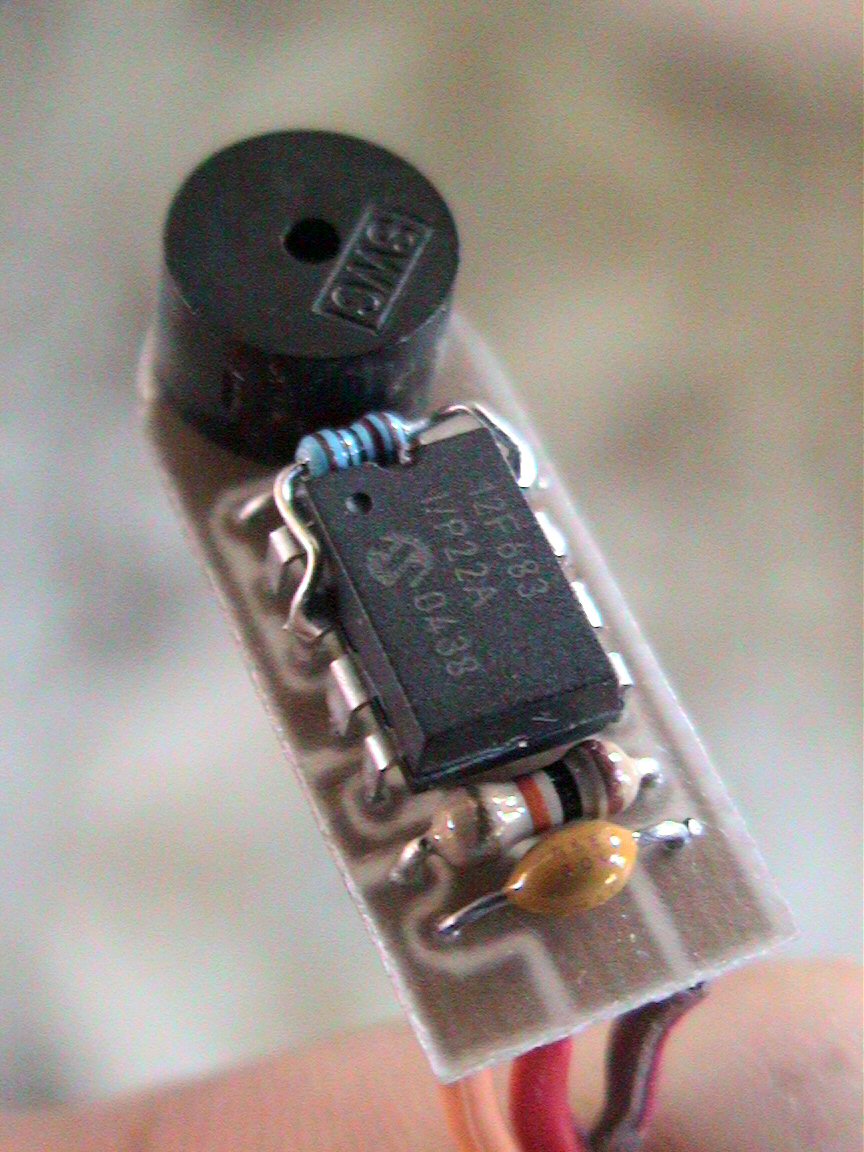
I designed this nifty circuit using a preprogrammed PIC microcontroller, a piezo
element, two 10K ohm resistors, one .1uF capacitor and one 1N4148 signal diode
(5 parts total).
This neat device allows you to program switch-on points and switch/stick
direction. The unit even stores the settings in internal memory. If
the circuit senses that there exists no servo signal, a piezo beeper is
repeatedly sounded.
This can be used as a model-finder. Next time your plane gets
lost in the high grass, you can simply turn off your transmitter and a second
later, the beeper continually emits beeps, allowing you to locate the downed
plane. The circuit also has a built in trigger delay that does not allow
the Aiptek camera to attempt to take pictures faster than it can store
them to memory. These user-programmable functions are very easy to use.
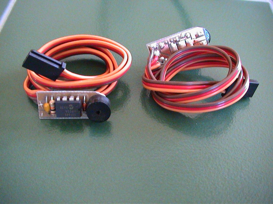
Newer pictures coming soon !! (new circuit/PCB
design as shown below)
..more coming soon


 Latest
pictures are shown below (Version 12):
Latest
pictures are shown below (Version 12):
Note: The 1/8 watt 10K resistor (blue in color)
soldered to Pins #1 and #8 is required. It is recommended that you solder
it directly to the PIC pins as shown. The PCB includes holes for mounting
the resistor on the bottom of the board but I believe it does not fit in he
camera easily.
Parts & Tools List
...
1) One
(1) Pre-programmed PIC chip
2) One (1) .1uF capacitor (tantalum)
3) Two (2) 10K Resistors
4) One (1) 1N4148 Signal Diode
Building Instructions...
Assembly of the Pic-based camera shutter switch
is fairly straight forward. Use the picture/diagrams on this webpage to
facilitate the quick assembly.
OK!... It's time to open the camera case and add the
three tiny wires needed to connect to this AipAxe R/C switch.
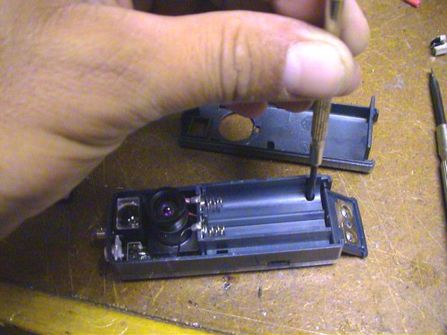
 Open
the battery compartment door slightly until you can see the
retaining screw and remove with a small
Philips screwdriver (a magnetized one will save you lots of trouble (such as
loosing the tiny irreplaceable screw). Once this screw is removed, the top
case section can usually be removed from the camera by gently running your
finger nail along the seam. It might take a bit of fussing but for the
most part, it comes off in a "snap".
Open
the battery compartment door slightly until you can see the
retaining screw and remove with a small
Philips screwdriver (a magnetized one will save you lots of trouble (such as
loosing the tiny irreplaceable screw). Once this screw is removed, the top
case section can usually be removed from the camera by gently running your
finger nail along the seam. It might take a bit of fussing but for the
most part, it comes off in a "snap".
NOTE: Before removing the top case section, adjust
the lens focus such that it is set for infinity (clockwise). Remember this
as when you replace the top case section, you can be assured that the focus
setting is retained. Also, once the top case section is removed, be sure
not to touch the focus lens. Doing so will alter the correct focus and
will require unnecessary refocusing.
Next, using a small Philips screw driver,
remove the two screws attaching the
middle case section to the bottom case section. Again, be careful not to
loose these screws (I use a magnet attached to my workbench to retain these tiny
screws.... never lost one since).
Once these screws are removed, you should be able to
detach the middle case section from
the lower case section. Be careful not to break any of the attached
battery wires. Simply rotate the middle case section and lay it along side
the bottom case section.
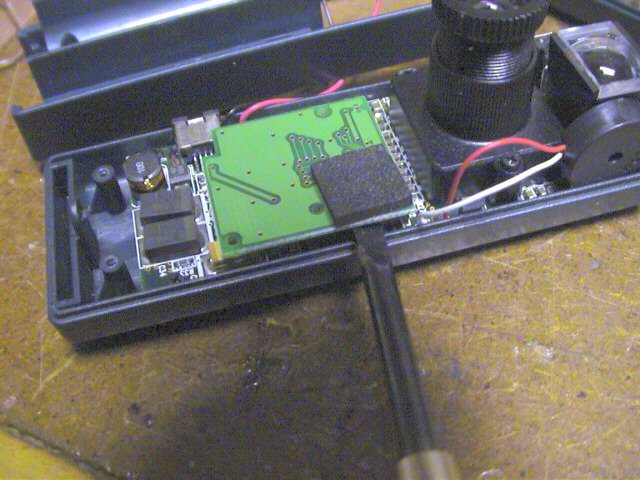
With the middle case section removed, locate the removable memory
card. I used a small plain screw driver to
gently pry the board up from its socket.
You can also gently grasp the board with your fingers and rock it back and forth
to remove.
NOTE: BE VERY CAREFUL IN REMOVING THIS AS "STATIC
ELECTRICITY" WILL RENDER YOU CAMERA USELESS !!.
Ground yourself or better
yet, use a grounded ESD strap.
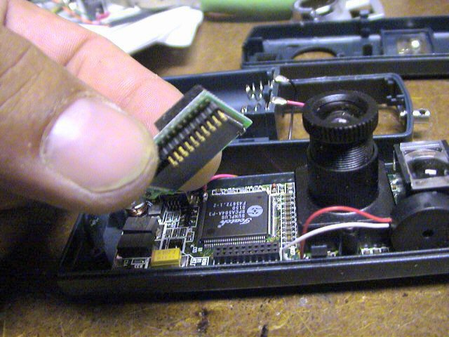
Once pried, gently remove
the memory board and place it in a safe non-static location (preferably a
anti-static bag). Without this daughterboard, you camera is useless.
Removing this memory board will gain you clear access to the USB connector.
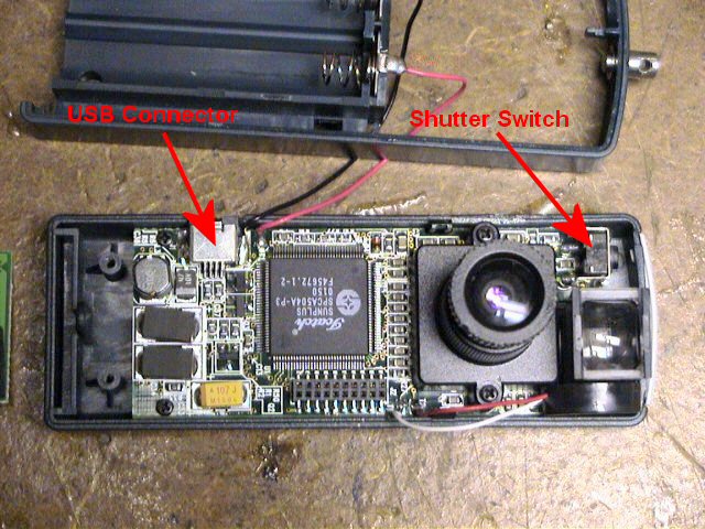
The picture to the left indicates
the location of the USB connector and the
camera's shutter switch connections. The shutter switch has two
connections, one to ground and one to the camera processor. We only need
to make a connection to the switch pin that is connected to the processor (the
pin closest to the outside of the camera).
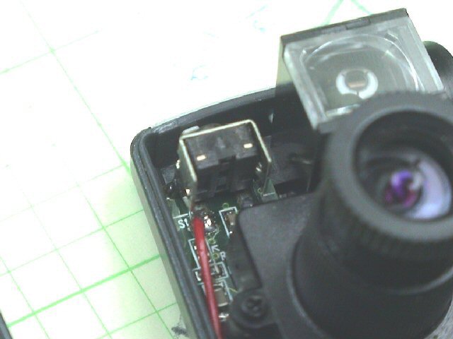 Using
a small piece of insulated wire and a small tipped soldering iron,
solder the wire to the switch connection
as shown. After soldering, you can test the connection by temporarily
installing the batteries, waiting for the camera to beep (powered and ready) and
then touching this wire to ground (the metal case part of the switch is fine).
If properly connected, this should force the camera to take a picture and beep.
Using
a small piece of insulated wire and a small tipped soldering iron,
solder the wire to the switch connection
as shown. After soldering, you can test the connection by temporarily
installing the batteries, waiting for the camera to beep (powered and ready) and
then touching this wire to ground (the metal case part of the switch is fine).
If properly connected, this should force the camera to take a picture and beep.
NOTE: To properly test, you will need to temporarily
reinstall the memory board first.
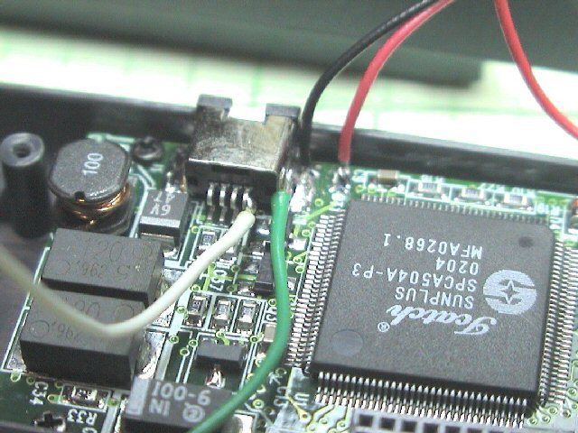
Next, connect two pieces of
wire to the USB connector. One wire will connect to ground (the metal
casing of the USB connector). The other connection can be a little tricky.
You need to make a connection to the outside pin (#1) of the USB connector.
You need to be VERY CAREFUL in making this connection as again, it can render
your camera useless. Such that you have adequate space, make the
connection to the USB pin first (then connect USB ground connection).
First, tin the end of your insulated wire and trim it such that the exposed
tinned wire is approximately 1/16". You can also dab a little flux onto
the USB pin prior to soldering. This will help facilitate the quick
soldering of the wire. Touch the tinned wire to the outside of the USB
pin, then gently apply your soldering iron to the tinned wire.
NOTE: DO NOT APPLY TOO MUCH PRESSURE TO THE WIRE/USB
CONNECTOR ! Doing so will most likely break the connection from the USB pin
to the camera board and you will then be unable to use the USB connector for
downloading pictures. Trust me,,, I have done this..... ONCE!.
Apply enough heat to the wire such the it gently connects to the
USB lead. After making this connection, you can again test the camera to
be assured it is still working properly (you might want to also check the USB
connector by attaching it to your PC and downloading pictures).
NOTE: To properly test, you will need to temporarily
reinstall the memory board first.
After being assured that it is connected and the camera is still
functional, make the ground connection to the USB metal case (you might have to
use some additional heat to get it to connect)... phew..... the tough part is
now done!
I usually then apply some
hot melt glue (or such) to the USB connection just to be certain that
excessive vibration does not bother the connection. I highly recommend
this step as it can not hurt. The glue will also allow you to manipulate
the wire without having to worry about breaking the connection or worse yet,
break the USB connection to the camera board.
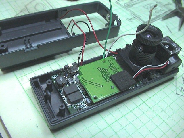
Then, carefully reinstall
the memory board by aligning the pins/socket and gently press it into place
(press on the foam piece attached to the top of the memory board. Be careful not
to pinch the wires you connected. You should lead the wires out from under
the memory board, towards the location where the R/C switch circuit will be located (left side
of lens, just below the shutter switch)
Feed these wires through the middle case section as you reinstall
it, being careful not to pinch the wires. Be sure to properly reinstall
the silver plastic shutter button if it had fallen out during disassembly.
It simply fits into two pivot guides located on the middle case section.
Check its operation before continuing. Reinstall the
two tiny screws,
attaching the middle case section to the bottom case section.
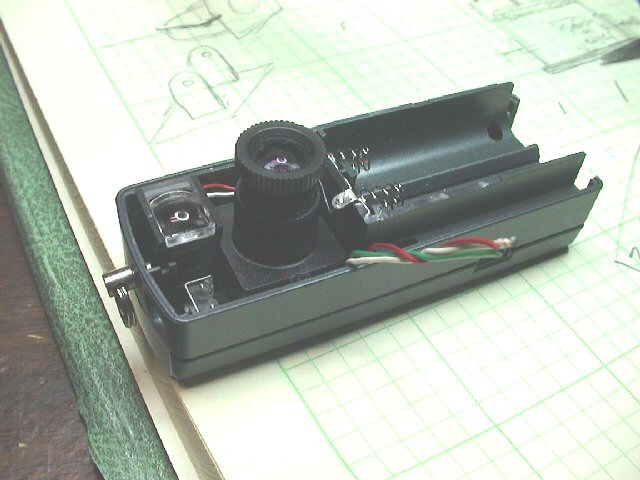
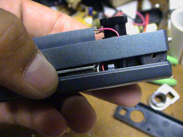
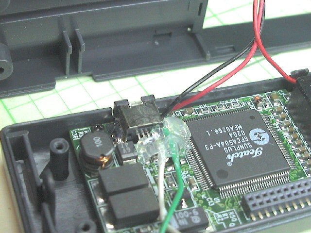
This picture is taken from another angle so that you can see
where the wires need to exit.
All we need to do now is assemble the circuit that will connect
to these three wires.
Take a break,... the hard part is actually
completed!
Now, observe the diagram to the left. These
are the connection points that need to be made. The three wires connected
to your camera are Power, Ground and shutter signals. Connect the
corresponding wires you previously attached to the camera... to the Aipaxe
switch as shown.
After making these three connections (don't yet stick in camera and assemble...
we need to test), plug the Aipaxe servo wire into your receiver. Turn on
your transmitter and adjust the channel on your transmitter (one that will
control switch) such that it is in the OFF position (toggle switch can be up or
down). Connect a battery to your receiver. This should not only
power up your receiver but also power up the switch. You should hear a
double beep and also notice the camera's display is lit. If it is not lit,
unplug the Aipaxe servo plug and try again. If the camera does not power
up but you hear the switch double beep, there is an issue with the connection to
the camera. If everything appears normal, try to flip the switch
momentarily and see if the camera takes a picture (display should indicate
increment of pictures taken).
If this works properly, neatly tuck the switch into
the camera (shorten wires if needed) and reassemble the camera.
Firmware/Code...
Click here to
View Code (Sorry, firmware is no longer freeware)
Click here to
Download Code (Sorry, firmware is no longer freeware)
CHECK
BACK LATER.... I WILL BE ADDING FREE CODE "SNIPPETS" !!
Testing and Operation Instructions...
DOWNLOAD THE MANUAL (MS WORD)
1. With both the transmitter
and receiver powered off, plug the camera's servo plug into the receiver channel
# to which you want to use as your shutter control. This can either be a switch
or joystick.
2. Power up the transmitter
first and position the switch or stick (corresponding to channel on receiver
which switch is connected) in the direction to which you would want to be the
OFF position (the position where no picture is taken).
3. Now power up the receiver and
you will hear the switch and Aiptek camera eventually power up (beeps).
About a second or two after that (as the circuit analyzes the receiver servo
signal), you will hear a "Ready" beep (2 low beeps then a longer high beep)
indicating that the circuit is ready for operation (no others beeps should be
heard until you take a picture).
IS THAT SIMPLE ?
4. To take a picture, move
the joystick/switch to the On position and then return it to the opposite (OFF)
position. You should hear the switch circuit output a low to high chirp, and
then quickly hear the Aiptek camera take a picture (also visible on the Aiptek
display). If the transmitter's switch/joystick if left in the ON position, the
switch circuit will make the Aiptek camera take a picture approximately every 7
seconds, until the switch/joystick is returned to the OFF position.
5. If you were to turn
off the transmitter while the receiver and camera are powered up, the switch
circuit will eventually continually beep, indicating that there exists no servo
signal. This is the built-in "Model-Finder" alarm that will hopefully help
you locate a downed aircraft. Just power off the transmitter and the
circuit will begin to beep.
6. Upon powering up the
transmitter, you will eventually hear a "Ready" beep (2 low beeps then a longer
high beep) indicating that the circuit is ready for operation once again.
Additional Notes...
 |
The circuit saves the last
user-programmed settings (trigger point and trigger direction) for use next
time you power it up. In order for the circuit to use these saved settings,
you MUST power up the transmitter before powering up the camera and receiver.
If you do not, you will have to reprogram the settings, which only takes 5
seconds the most.
|
|
Aiptek cameras can be
funny in that some are particularly sensitive to input voltage. Most Aiptek
cameras
I have modified work fine on 5V and even 5.5 volts.
If you try to power up
the camera from the receiver and the receiver is powered using 5 cells (6
volts), the camera will probably not turn on, and you in fact might damage the
PIC switch circuit. Some work, some don’t. It is
highly recommended that you power up the receiver/camera using either a 4 cell
battery pack (4.8-5.2 volts) or use a Battery Elimination Circuit (BEC) or
voltage regulator that outputs a regulated 5 volts.
|
|
When you connect the
camera up to your computer to download pictures (via USB cable), the camera
and switch circuit are powered up. Because the circuit senses NO servo
signal, the model-finder alarm will beep continuously as you are downloading
pictures. The download process is not affected by this beeping.
Once the downloading is complete, simply unplug the USB cable from the camera.
|
|
This mod originally was
designed such that the camera could still be powered and operated with two AAA
batteries. After modifying a bunch of these cameras, I have noticed that
some work normally with batteries installed but some do not. I therefore
can not guarantee that the camera will operate properly with batteries
installed. The intention of this modification was to make an R/C
controlled aerial camera using a miniature hand-help digital camera. I
can guarantee that this mod will do just that!
|
|
There has
been rare occurrences where an Aiptek camera can simply go "berserk"...., i.e.
continual beeping or just does not work at all (indicated some times by all
"eights" (888) in the camera display). In this case, it is good to reset the
camera by hold down the "mode" and "shutter" buttons simultaneously for
several seconds until a beep is heard (do this while camera is powered up).
Removing power for a few seconds and reapplying has some times fix the
problem too. |
**** VERY LIMITED
QUANTITIES ARE AVAILABLE ****
Please
email me regarding product
availability before sending money....
Click Here to visit the


Earthmen
Productions
© Dec-00-Mar-12
